
Page 422 - Keubler Motion Sensors
P. 422
Linear measuring technology
Draw wire mechanics Measuring length max. 6 m
with encoder or analogue sensor Draw wire encoder C120 Traverse speed max. 10 m/s
www.HydroSanatSharif.com
Order code D8.3C1 . 0600 . XXX X . 0000
with analogue sensor Type a b c
a Measuring range b Analogue sensor output / power supply Optional on request
0600 = 6000 mm A11 = 4 ... 20 mA / 12 ... 30 V DC - Other measuring ranges
A22 = 0 ... 10 V / 12 ... 30 V DC - Cable diameter 1 mm
A33 = potentiometer 1 k1 / max. 30 V DC - Ring eye instead of cable clip
- Modified cable and/or connector orientation
c Type of connection - Modified cable outlet direction
1 = axial cable, 2 m [6.56‘] PVC - Sensor protection level IP67
3 = M12 connector, 4-pin - Increased linearity
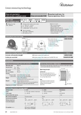
Guide pulley for draw wire encoder Order no.
Order code for the set: 8.0000.7000.0045
- Guide pulley (anodised aluminium)
- 2 x countersunk screws
for lateral fixing
- 2 x hexagonal screws
for fixing on a flat surface
Connection technology for analogue sensor Order no.
Connector, self-assembly (straight) M12 female connector with coupling nut 8.0000.5116.0000
Cordset, pre-assembled M12 female connector with coupling nut, 2 m [6.56‘] PVC cable 05.00.6081.2211.002M
Technical data
Mechanical characteristics (draw wire mechanics) Electrical characteristics (digital output)
Measuring range 6000 mm The electrical characteristics of the draw wire mechanics with digital output
Extension force F min 8.8 N can be found in the data sheets of the encoders
F max 12.3 N Drum width
Operating principle
Max. speed. 10 m/s
Max. acceleration 140 m/s 2 Construction
The core of a draw wire device is a
Linearity
analogue output ±0.1 % (of the measuring range) drum mounted on bearings, onto which
with encoder ±0.05 % (of the measuring range) a wire is wound. Winding takes place Drum diameter
via a spring-loaded device.
Weight approx. 1600 g [56.44 oz]
(depending on the sensor/encoder used) Note
Material housing titanium-anodised aluminium Exceeding the maximum extension
wire stainless steel ø 0.5 mm (ø 1 mm can be supplied as length of the draw wire will lead to
a special up to measuring range 3000 mm) damage to the wire and the
Wire diameter
Protection selon EN 60529 IP65 (sensor) mechanics.
Electrical characteristics (analogue output)
Analogue output 0 ... 10 V 4 ... 20 mA Potentiometer
Output 0 ... 10 V / galv. isolated, 4 conductors 4 ... 20 mA / 2 conductors 1 k1
Power supply 12 ... 30 V DC 12 ... 30 V DC max. 30 V DC
Recommended slider current – – < 1 µA
Max. current consumption 22.5 mA (no load) 50 mA –
Reverse polarity protection yes yes –
Working temperature -20°C ... +60°C [-4°F ... +140°F] -20°C ... +60°C [-4°F ... +140°F] -20°C ... +85°C [-4°F ... +185°F]
Connection diagrams
V+ + V V+ out V+ + V+ V+ + V V+
out
- GNDout - A -
0 V out 0 V
CE compliant acc. to EMC guideline 2004/108/EC
RoHS guideline 2011/65/EU
420 www.kuebler.com © Fritz Kübler GmbH, subject to errors and changes. 02/2015