
Page 396 - Keubler Motion Sensors
P. 396
Linear measuring technology
Absolute magnetic measurement system Measuring length max. 8 m
sensor head, magnetic band Limes LA10 / BA1 Resolution min. 1 µm
www.HydroSanatSharif.com
Magnetic band Limes BA1
Pole gap basic pole pitch 1 mm Working temperature -20°C ... +70°C [-4°F ... +158°F]
Dimensions width 10 mm (in case of mounting with adhesive
thickness 1.97 mm incl. masking tape tape only)
Relative linear expansion 6L = L x _ x 6b Storage temperature -20°C ... +80°C [-4°F ... +176°F]
Mounting adhesive joint
L = measuring length in meters Additional length 100 mm
-6
_ = 16 x 10 1/K in order to obtain an optimal
temperature coefficient measuring result, the magnetic band
6b = relative temperature change should be about 0.1 m longer than
based on 20°C [+68°F] in °K the required measuring length
Min. bending radius for storage * 150 mm
Material metal tape precision steel strip 1.4404
acc. to EN 10088-3
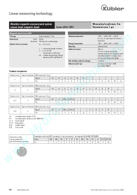
Terminal assignment
Output circuit Type of connection M12 connector, 12 pin
Signal: 0 V +V C+ C- D+ D- – – – – – –
1 2
Pin: 1 2 3 4 5 6 7 8 9 10 11 12
Output circuit Type of connection M12 connector, 12 pin
Signal: 0 V +V C+ C- D+ D- A B – –
2 2
Pin: 1 2 3 4 5 6 7 8 9 10 11 12
Output circuit Type of connection M12 connector, 12 pin
Signal: 0 V +V CAN_L CAN_H – – – – – – – –
3, 4 2
Pin: 1 2 3 4 5 6 7 8 9 10 11 12
Output circuit Type of connection M12 connector, 12 pin
Signal: 0 V +V CAN_L CAN_H – – A B – –
5, 6 2
Pin: 1 2 3 4 5 6 7 8 9 10 11 12
+V: Encoder power supply +V DC
0 V: Encoder power supply ground GND (0 V)
C+, C-: Clock signal
D+, D-: Data signal
A, : Cosine signal
B, : Sine signal
Connection cable with M12 connector, 12 pin (accessory) – for example 05.00.60B1.B211.005M
Connection cable
colour assignment Colour: WH BN GN YE GY PK BU RD BK VT GY / PK RD / BU
with M12 female connector
Pin: 1 2 3 4 5 6 7 8 9 10 11 12
2 3
4
1 10 11 5
9 12
8 7 6
394 www.kuebler.com © Fritz Kübler GmbH, subject to errors and changes. 02/2015