
Page 392 - Keubler Motion Sensors
P. 392
Linear measuring technology
Incremental magnetic measurement system
sensor head, magnetic band Limes LI50 / B2 Resolution min. 5 µm
www.HydroSanatSharif.com
Accessories / Display type 572 Order no.
Position display, 6-digit with 4 fast switch outputs
and serial interface 6.572.0116.D05
with 4 fast switch outputs, serial interface and
scalable analogue output 6.572.0116.D95
Position display, 8-digit with 4 fast switch outputs
and serial interface 6.572.0118.D05
with 4 fast switch outputs, serial interface and
scalable analogue output 6.572.0118.D95
Further accessories can be found in the accessories section or in the accessories area of our website at: www.kuebler.com/accessories.
Additional connectors can be found in the connection technology section or in the connection technology area of our website at: www.kuebler.com/connection_technology.
Technical data
Sensor head Limes LI50 Magnetic band Limes B2
Output circuit Push-Pull RS422 Pole gap 5 mm from pole to pole
Power supply 4.8 ... 30 V DC 4.8 ... 26 V DC Dimensions width 10 mm
Permissible load / channel ±20 mA 120 1 thickness 1.97 mm incl. masking tape
-6
Temperature coefficient 16 x 10 /K
Max. cable length max. 30 m RS422 standard
Power consumption typ. 25 mA, max. 60 mA Working temperature -20°C ... +80°C [-4°F ... +176°F]
(no load) -20°C ... +65°C [-4°F ... +144°F]
(when mounted solely with adhesive tape)
1)
Short circuit proof yes yes 2)
Storage temperature -20°C ... +80°C [-4°F ... +176°F]
Min. pulse edge interval 1 µs (corresponds to 4 µs/cycle see signal figures below)
Mounting adhesive joint
Output signal A, , B, , 0,
Measuring 0.1 m (to receive an optimal result of measure-
Reference signal index periodical
ment, the magnetic band should be ca. 0.1 m
longer than the desired measuring length)
Accuracy
Bending radius * 150 mm
System accuracy typ. +200 µm, max. ± (0.06 + 0.04 x L) mm,
L in [m], up to L = 50 m, at T = 20°C [+68°F] (when mounted solely with adhesive tape)
Material metal tape precision steel strip 1.4404 acc. to EN 10088-3
Repeat accuracy ±1 increment
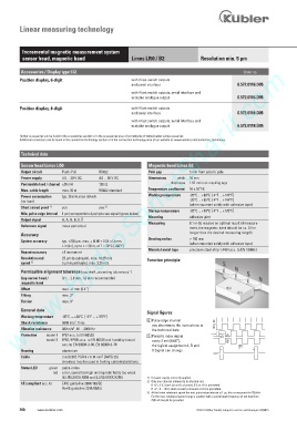
Resolution and 25 µm (quadruple), max. 16.25 m/s Function principle
3)
speed 5 µm (quadruple), max. 3.25 m/s
Permissible alignment tolerance (see draft „mounting tolerances“)
Gap sensor head / 0.1 ... 2.0 mm, 1.0 mm recommended
magnetic band
Offset max. ±1 mm [0.4“]
Tilting max. 3°
Torsion max. 3°
General data
Signal figures
Working temperature -20°C ... +80°C [-4°F ... +176°F]
8 Pulse edge interval:
2
Shock resistance 5000 m/s , 1 ms
pay attention to the instructions in
2
Vibration resistance 300 m/s , 10 ... 2000 Hz the technical data
Protection model 1 IP67 acc. to EN 60529 9 Periodic index signal 8
model 2 IP68 / IP69k acc. to EN 60529 and humidity tested every 2 mm [0.08“];
acc. to EN 60068-3-38, EN 60068-3-78 the logical assignment A, B and 9
Housing aluminium 0-Signal can change
2
Cable 2 m [6.56‘] PUR 8 x 0.14 mm [AWG 25]
shielded, may be used in trailing cable installations
Status LED green pulse-index
red error; speed too high or magnetic fields too weak
(8.LI50.XXXX.X050 and 8.LI50.XXXX.X250) 1) If power supply correctly applied.
2) Only one channel allowed to be shorted-out.
CE compliant acc. to EMC guideline 2004/108/EC
If +V = 5 V, short-circuit to channel, 0 V, or +V is permitted.
RoHS guideline 2011/65/EU If +V = 5 ... 30 V, short-circuit to channel or 0 V is permitted.
3) At the listed rotational speed the min. pulse edge interval is 1 µs, this corresponds to 250 kHz.
For the max. rotational speed range a counter with a count input frequency of not less then
250 kHz should be provided.
390 www.kuebler.com © Fritz Kübler GmbH, subject to errors and changes. 02/2015