
Page 168 - Keubler Motion Sensors
P. 168
Absolute encoders - singleturn
Compact
magnetic Sendix M3658 / M3678 (shaft / hollow shaft) SAE J1939
www.HydroSanatSharif.com
Interface characteristics CANopen
Resolution 1 ... 16384 (14 bit), scalable
default: 16384 (14 bit)
Code binary
Interface CAN high-speed acc. to ISO 11898,
Basic- and Full-CAN,
CAN specification 2.0 B
Protocol SAE J1939
Node address 1 ... 255
via address claiming
Baud rate 250 kbit/s
Termination software configurable
General information concerning SAE J1939 Encoder implementation SAE J1939
The protocol J1939 originates from the international Society of Automotive • PGNs that are adaptable to the customer’s application.
Engineers (SAE) and operates on the physical layer with high speed CAN as • Resolution of address conflicts -> Address Claiming (ACL).
per ISO11898. The application emphasis lies in the area of the power train
and chassis of commercial vehicles. It serves to transfer diagnostic data (for • Continuous checking whether control addresses have been assigned twice
example, motor speed, position, temperature) and control information. Type within a network.
series M3658 and M3678 encoders support the total functionality of J1939. • Change of control device addresses during run-time.
This protocol is a multimaster system with decentralised network management • Unique identification of a control device with the help of a name that is
that does not involve channel-based communication. unique worldwide. This name serves to identify the functionality of a control
device in the network.
It supports up to 254 logic nodes and 30 physical control devices per segment.
The information is described as parameters (signals) and combined on 4 • Predefined PGs for position, speed and alarm.
memory pages (data pages) into parameter groups (PGs). Each parameter group • 250 kbit/s, 29 bit identifier.
can be identified via a unique number, the parameter group number (PGN). • Watchdog controlled device.
Independently of this, each signal is assigned a unique SPN (suspect parameter
number). A two-colour LED, located on the rear of the encoder, signals the operating and
fault status of the J1939 protocol, as well as the status of the internal sensor
The major part of the communication occurs cyclically and can be received by diagnostics.
all control devices without the explicit request for data (Broadcast). Furthermore
the parameter groups are optimised to a length of 8 data bytes. This enables
very efficient utilization of the CAN protocol. If greater amounts of data need
to be transferred, then transport protocols (TP) can be used: BAM (broadcast
announce message) and CMDT (connection mode data transfer). With BAM TP
the transfer of data occurs as a broadcast.
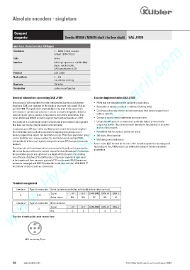
Terminal assignment
Interface Type of connection Cable (isolate unused wires individually before initial start-up)
Signal: +V 0 V CAN_GND CAN_H CAN_L
C 2, B
Cable colour: BN WH GY GN YE
Interface Type of connection M12 connector
Signal: +V 0 V CAN_GND CAN_H CAN_L
C 4
Pin: 2 3 1 4 5
Top view of mating side, male contact base
2
3 5 1
4
M12 connector, 5-pin
166 www.kuebler.com © Fritz Kübler GmbH, subject to errors and changes. 02/2015