
Page 61 - Keubler Motion Sensors
P. 61
Incremental encoders
Compact
optical 3610 / 3620 (shaft / hollow shaft) Push-Pull / RS422
www.HydroSanatSharif.com
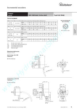
Terminal assignment
Output circuit Type of connection Cable (isolate unused wires individually before initial start-up) Top view of mating side,
male contact base
2, 4, 5, 6 Signal: 0 V +V A B 0
1, 2, E, A, B
with inv. signal Cable colour: WH BN GN YE GY PK BU RD
2
3
Output circuit Type of connection Cable (isolate unused wires individually before initial start-up) 4 8 1
3 Signal: 0 V +V A B 0 5 6 7
1, 2, E, A, B
without inv. signal Cable colour: WH BN GN - YE - GY -
M12 connector, 8-pin Incremental
Output circuit Type of connection M12 connector encoders
2, 4, 5, 6 Signal: 0 V +V A B 0
3, 4
with inv. signal Pin: 1 2 3 4 5 6 7 8
Output circuit Type of connection M12 connector
3 Signal: 0 V +V A B 0
3, 4
without inv. signal Pin: 1 2 3 - 5 - 7 -
+V: Encoder power supply +V DC
0 V: Encoder power supply ground GND (0 V)
A, : Incremental output channel A
B, : Incremental output channel B
0, : Reference signal
Dimensions shaft version
Dimensions in mm [inch]
Synchro flange, ø 36.5 [1.44]
Flange type 2
1 M3, 5 [0.20] deep
K > @ I /
'
PLQ 5 PD[
Clamping flange, ø 36.5 [1.44]
Flange type 3
1 M3, 5 [0.20] deep
36 > @ I ' > @ I
'
PLQ 5
PLQ 5 /
/
PD[ PD[
0 0
© Fritz Kübler GmbH, subject to errors and changes. 02/2015 www.kuebler.com 59