
Page 186 - Keubler Motion Sensors
P. 186
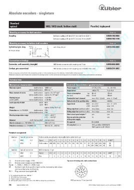
Absolute encoders - singleturn


          Standard
          optical                         5852 / 5872 (shaft / hollow shaft)     Parallel, highspeed
        www.HydroSanatSharif.com
         Mounting accessory for shaft encoders                                                     Order no.
         Coupling                                bellows coupling ø 19 mm [0.75“] for shaft 6 mm [0.24“]   8.0000.1102.0606
                                                 bellows coupling ø 19 mm [0.75“] for shaft 10 mm [0.39“]   8.0000.1102.1010

         Mounting accessory for hollow shaft encoders                                              Order no.
         Cylindrical pin, long                    with fixing thread                             8.0010.4700.0000

                                  6:  >    @  P
         for torque stops

                            0             5

         Connection technology                                                                     Order no.
         Connector, self-assembly (straight)     M23 female connector with coupling nut, 17-pin   8.0000.5042.0000

         Cordset, pre-assembled                  M23 female connector with coupling nut, 2 m [6.56‘] PVC cable   8.0000.6741.0002
         Further accessories can be found in the accessories section or in the accessories area of our website at: www.kuebler.com/accessories.
         Additional connectors can be found in the connection technology section or in the connection technology area of our website at: www.kuebler.com/connection_technology.

         Technical data
         Mechanical characteristics                          Electrical characteristics (parallel interface)
                                              -1
         Maximum speed         shaft version  12000 min       Power supply (+V)      5 V DC (±5 %)    10 ... 30 V DC
                                              -1 1)
                           hollow shaft version  6000 min      Output driver        CMOS-TTL    Push-Pull
                                                  -6
         Mass moment of inertia   shaft version  approx. 1.8 x 10  kgm   2  Power consumption    typ.   40 mA    100 mA
                                                 -6
                           hollow shaft version  approx. 6 x 10  kgm 2  (no load)   max.   75 mA    159 mA
         Starting torque        shaft version  < 0.01 Nm      Permissible load / channel      max. +0.5 / -2.0 mA    max. +/- 10 mA
         at 20°C [68°F]      hollow shaft version  < 0.05 Nm
                                                             Refresh rate of the position data     40000/s    40000/s
         Load capacity of shaft     radial  80 N
                                    axial  40 N              Signal level     HIGH   min. 3.4 V    min. +V - 2.8 V
                                                                              LOW   max. 0.3 V    max. 1.8 V
         Weight                          approx. 0.4 kg [14.11 oz]
                                                             Rising edge time t r  (without cable)    max. 0.2 µs    max. 1µs
         Protection acc. to EN 60529   shaft version  IP65
                           hollow shaft version  IP66        Falling edge time t f  (without cable)    max. 0.2 µs    max. 1µs
                                                             Short circuit proof outputs        yes   yes
                                                                             3)
         Working temperature range       -20°C ... +85°C  2)
                                          [-4°F ... +185°F]  2)  Reverse polarity protection       no    yes
                                                             of the power supply
         Material           shaft / hollow shaft  stainless steel
         Shock resistance acc. EN 60068-2-27        2500 m/s , 6 ms  UL approval       file 224618
                                              2
                                             2
         Vibration resistance acc. EN 60068-2-6     100 m/s , 10 ... 2000 Hz  CE compliant acc. to      EMC guideline 2004/108/EC
                                                                                   RoHS guideline 2011/65/EU
         Terminal assignment
            Interface   Type of connection   Cable (isolate unused wires individually before initial start-up)
             1, 3   5852:   1, 2    Signal   0 V   +V     1    2    3    4    5    6    7    8    9    10   11   12   13      14 (V/R)
                                                                                                     4)
                   5872:    1       Cable colour:   WH   BN    GN   YE   GY   PK   BU   RD   BK   VT   GY   RD   WH   BN   WH      YE
                                                                                PK   BU   GN   GN   YE      BN
            Interface   Type of connection   M23 connector, 17-pin
                                                                                                    4)
             1, 3   5852:   3, 5    Signal   0 V   +V    1    2    3    4    5    6    7    8    9    10   11   12   13    1 (V/R)         )
                   5872:    2       Pin:     1    2    3    4    5    6    7    8    9    10   11   12   13   14   15    16      17   PH
         +V:    Encoder power supply +V DC                   Top view of mating side, male contact base
         0 V:    Encoder power supply ground GND (0 V)
         Signal :   1 = MSB; 2 = MSB-1; 3 = MSB-2 usw.
         VR:    Up/down input. As long as this input is active, decreasing code values
               are transmitted when shaft turning
         PH ):   Plug connector housing (shield)

         1)  For continous operation max. 1500 min -1 .
         2)  70°C [158°F] for 14 bit version.
         3)  If power supply +V   correctly applied.
         4)   V/R only with output circuit 3 up to max. 13 bit. MSB to change the count direction.  M23 connector, 17-pin (parallel)
         184    www.kuebler.com                                                 © Fritz Kübler GmbH, subject to errors and changes. 02/2015