
Page 182 - Keubler Motion Sensors
P. 182
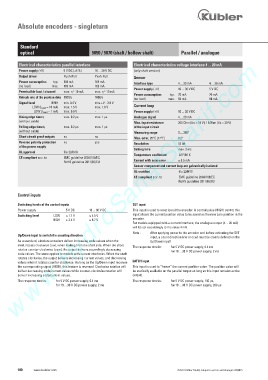
Absolute encoders - singleturn


          Standard
          optical                         5850 / 5870 (shaft / hollow shaft)     Parallel / analogue
        www.HydroSanatSharif.com
         Electrical characteristics parallel interface
         Electrical characteristics parallel interface       Electrical characteristics voltage interface 4 ... 20 mA
                             5 V DC (±5 %)
                                           10 ... 30 V DC
         Power supply (+V)  (+V)        5 V DC (±5 %)    10 ... 30 V DC  (only shaft version)
         Power supply
                                           Push-Pull
                             Push-Pull
         Output driver          Push-Pull    Push-Pull
         Output driver
                                                             Sensor
         Power consumption     typ.   109 mA     109 mA        Interface type     4 ... 20 mA    4 ... 20 mA
                                           109 mA
                             109 mA
                         typ.
         Power consumption
                                           169 mA
         (no load)
         (no load)      max.   169 mA      169 mA
                        max.
                             169 mA
                                                             Power supply (+V)     10 ... 30 V DC    5 V DC
                             max. +/- 10 mA
                                           max. +/- 10 mA
         Permissible load / channel        max. +/- 10 mA   max. +/- 10 mA
         Permissible load / channel
                                                             Power consumption    typ.  70 mA    70 mA
         Refresh rate of the position data  1 600/s    1600/s    1600/s  (no load)    max.   84 mA    84 mA
                                           1 600/s
         Refresh rate of the position data
                                           min. +V - 2.8 V
                             min. 3.4 V
         Signal level     HIGH   min. 3.4 V     min. +V - 2.8 V
                        HIGH
         Signal level
                             max. 1.5 V
                                           max. 1.8 V
                   LOW (l Load  = 10 mA)  = 10 mA)   max. 1.5 V     max. 1.8 V         Current loop
               LOW (l Load
                             max. 0.3 V
                   LOW (l Load  = 1 mA)  = 1 mA)   max. 0.3 V     - -  Power supply (+V)     10 ... 30 V DC
                LOW (l Load
                             max. 0.2 µs
         Rising edge time t r              max. 0.2 µs     max. 1 µs        Analogue signal      4 ... 20 mA
                                           max. 1 µs
         Rising edge time t r
         (without cable)
         (without cable)
                                                             Max. input resistance      200 Ohm (Us = 10 V), 1 kOhm (Us = 30 V)
                                           max. 1 µs
                             max. 0.2 µs
         Falling edge time t f              max. 0.2 µs     max. 1 µs         of the input circuit
         Falling edge time t f
         (without cable)
         (without cable)                                     Measuring range     0 ... 360°
                             no
         Short circuit proof outputs        no   no          Max. error, 25°C [77°F]     0.2°
                                           no
         Short circuit proof outputs
                             no
                                           yes
         Reverse polarity protection         no   yes        Resolution          13 bit
         Reverse polarity protection
         of the power supply
         of the power supply
                                                             Setting time        max. 2 ms
                             file 224618
         UL approval            file 224618
         UL approval
                                                             Temperature coefficient       0.1°/10 K
                               EMC guideline 2004/108/EC
         CE compliant acc. to acc. to          EMC guideline 2004/108/EC
         CE compliant
                                RoHS guideline 2011/65/EU    Current with scan error      ) 3.5 mA
                             RoHS guideline 2011/65/EU
                                                             Sensor component and current loop are galvanically isolated
                                                             UL-certified         file 224618
                                                             CE compliant acc. to        EMC guideline 2004/108/EC
                                                                                 RoHS guideline 2011/65/EU
         Control inputs
         Switching levels of the control inputs             SET input
         Power supply          5 V DC    10 ... 30 V DC     This input is used to reset (zero) the encoder. A control pulse (HIGH) sent to this
         Switching level   LOW   ) 1.7 V   ) 4.5 V          input allows the current position value to be saved as the new zero position in the
                         HIGH   * 3.4 V   * 8.7 V           encoder.
                                                            For models equipped with a current interface, the analogue output (4 ... 20 mA)
                                                            will be set accordingly to the value 4 mA.
                                                            Note :   After applying power to the encoder and before activating the SET
         Up/Down input to switch the counting direction
                                                                    input, a count direction (cw or ccw) must be clearly defined on the
         As a standard, absolute encoders deliver increasing code values when the        Up/Down input!
         shaft rotates clockwise (cw), when looking from the shaft side. When the shaft   The response time is:    for 5 V DC power supply, 0.4 ms
         rotates counter-clockwise (ccw), the output delivers accordingly decreasing           for 10 ... 30 V DC power supply, 2 ms
         code values. The same applies to models with current interfaces. When the shaft
         rotates clockwise, the output delivers increasing current values, and decreasing
         values when it rotates counter-clockwise. As long as the Up/Down input receives   LATCH input
         the corresponding signal (HIGH), this feature is reversed. Clockwise rotation will   This input is used to “freeze” the current position value. The position value will
         deliver decreasing code/current values while counter-clockwise rotation will   be statically available on the parallel output as long as this input remains active
         deliver increasing code/current values.            (HIGH).
         The response time is:   for 5 V DC power supply, 0.4 ms  The response time is:    for 5 V DC power supply, 140 µs,
                          for 10 ... 30 V DC power supply, 2 ms              for 10 ... 30 V DC power supply, 200 µs
         180    www.kuebler.com                                                 © Fritz Kübler GmbH, subject to errors and changes. 02/2015