
Page 191 - Keubler Motion Sensors
P. 191
Absolute encoders - singleturn
Standard
optical Sendix 5853 / 5873 (shaft / hollow shaft) SSI / BiSS
www.HydroSanatSharif.com
DIR input Power-ON time
A HIGH signal switches the direction of rotation from the default CW to CCW. After Power-ON the encoder requires a time of approx. 150 ms before valid data
This function can also be factory-programmed to be inverted. If DIR is changed can be read.
when the device is already switched on, then this will be interpreted as an
error. The LED will come ON and the status output will switch to LOW.
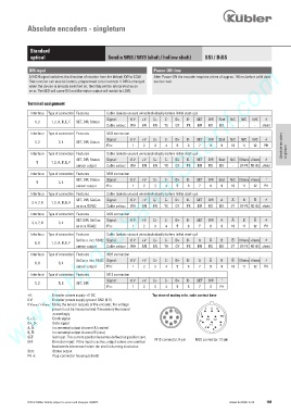
Terminal assignment
Interface Type of connection Features Cable (isolate unused wires individually before initial start-up)
Signal: 0 V +V C+ C- D+ D- SET DIR Stat N/C N/C N/C )
1, 2 1, 2, A, B, E, F SET, DIR, Status
Cable colour: WH BN GN YE GY PK BU RD BK - - - shield
Interface Type of connection Features M23 connector
Signal: 0 V +V C+ C- D+ D- SET DIR Stat N/C N/C N/C )
1, 2 3, 4 SET, DIR, Status
Pin: 1 2 3 4 5 6 7 8 9 10 11 12 PH Absolute encoders
Interface Type of connection Features Cable (isolate unused wires individually before initial start-up) singleturn
SET, DIR, Status Signal: 0 V +V C+ C- D+ D- SET DIR Stat N/C 0 Vsens +Vsens )
5 1, 2, A, B, E, F
sensor output Cable colour: WH BN GN YE GY PK BU RD BK - GY-PK RD-BU shield
Interface Type of connection Features M23 connector
SET, DIR, Status Signal: 0 V +V C+ C- D+ D- SET DIR Stat N/C 0 Vsens +Vsens )
5 3, 4
sensor output Pin: 1 2 3 4 5 6 7 8 9 10 11 12 PH
Interface Type of connection Features Cable (isolate unused wires individually before initial start-up)
SET, DIR, SinCos Signal: 0 V +V C+ C- D+ D- SET DIR A B )
3, 4, 7, 8 1, 2, A, B, E, F
or incr. RS422 Cable colour: WH BN GN YE GY PK BU RD BK VT GY-PK RD-BU shield
Interface Type of connection Features M23 connector
SET, DIR, SinCos Signal: 0 V +V C+ C- D+ D- SET DIR A B )
3, 4, 7, 8 3, 4
or incr. RS422 Pin: 1 2 3 4 5 6 7 8 9 10 11 12 PH
Interface Type of connection Features Cable (isolate unused wires individually before initial start-up)
SinCos o. incr. RS422 Signal: 0 V +V C+ C- D+ D- A B 0 Vsens +Vsens )
6, 9 1, 2, A, B, E, F
sensor output Cable colour: WH BN GN YE GY PK BU RD BK VT GY-PK RD-BU shield
Interface Type of connection Features M23 connector
SinCos o. incr. RS422 Signal: 0 V +V C+ C- D+ D- A B 0 Vsens +Vsens )
6, 9 3, 4
sensor output Pin: 1 2 3 4 5 6 7 8 9 10 11 12 PH
Interface Type of connection Features M12 connector
Signal: 0 V +V C+ C- D+ D- SET DIR )
1, 2 5, 6 SET, DIR
Pin: 1 2 3 4 5 6 7 8 PH
+V: Encoder power supply +V DC Top view of mating side, male contact base
0 V: Encoder power supply ground GND (0 V)
0 Vsens / +Vsens: Using the sensor outputs of the encoder, the voltage
present can be measured and if necessary increased 2 1 9 8
accordingly. 3 2
C+, C-: Clock signal 4 8 1 3 10 12 7
D+, D-: Data signal 5 6 7 11 6
A, : Incremental output channel A (cosine) 4 5
B, : Incremental output channel B (sine)
SET: Set input. The current position becomes defined as position zero.
DIR: Direction input: If this input is active, output values are counted M12 connector, 8-pin M23 connector, 12-pin
backwards (decrease) when the shaft is turning clockwise.
Stat: Status output
PH ): Plug connector housing (shield)
© Fritz Kübler GmbH, subject to errors and changes. 02/2015 www.kuebler.com 189