
Page 160 - Keubler Motion Sensors
P. 160
Absolute encoders - singleturn
Compact
magnetic Sendix 3651 / 3671 (shaft / hollow shaft) Analogue
www.HydroSanatSharif.com
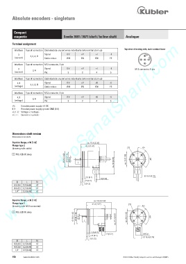
Terminal assignment
Interface Type of connection Cable (isolate unused wires individually before initial start-up) Top view of mating side, male contact base
3 Signal: 0 V +V +I -I 2
(current) 1, 2, A, B Cable colour: WH BN GN YE
3 5 1
Interface Type of connection M12 connector, 5 pin 4
3 Signal: 0 V +V +I -I M12 connector, 5-pin
(current) 3, 4 Pin: 3 2 4 5
Interface Type of connection Cable (isolate unused wires individually before initial start-up)
4, 5 Signal: 0 V +V +U -U
(voltage) 1, 2, A, B Cable colour: WH BN GN YE
Interface Type of connection M12 connector, 5 pin
4, 5 Signal: 0 V +V +U -U
(voltage) 3, 4 Pin: 3 2 4 5
+V : Encoder power supply +V DC
0 V : Encoder power supply ground GND (0 V)
+U / -U : Voltage + / voltage -
+I / -I : Current + / current -
Dimensions shaft version
Dimensions in mm [inch]
Synchro flange, ø 36 [1.42] ca. 57,8 [2.28]
Flange type 2 42,3 [1.67]
(drawing with cable) 1 45°
1 M3, 6 [0.24] deep
Ø 36 [1.42] Ø 33 [1.3] Ø D h7 X L ca. 52 [2.05] ca. 26 [1.02] 90°
Ø 18,8 [0.74]
2,5 [0.1]
8 [0.32]
D L Fit 2,5 [0.1]
6 [0.24] 12.5 [0.49] h7 3 [0.12]
8 [0.32] 12.5 [0.49] h7
1/4“ 12.5 [0.49] h7
Synchro flange, ø 36 [1.42] ca. 56,3 [2.22]
Flange type 2 42,3 [1.67] 1
(drawing with M12 connector) 45°
1 M3, 6 [0.24] deep
Ø 36 [1.42] Ø 33 [1.3] Ø D h7 X L ca. 51,5 [2.03] ca. 26 [1.02] 90°
2,5 [0.1]
8 [0.32] M12x1
2,5 [0.1]
Ø 18,8 [0.74]
3 [0.12]
D L Fit
6 [0.24] 12.5 [0.49] h7
8 [0.32] 12.5 [0.49] h7
1/4“ 12.5 [0.49] h7
158 www.kuebler.com © Fritz Kübler GmbH, subject to errors and changes. 02/2015