
Page 157 - Keubler Motion Sensors
P. 157
Absolute encoders - singleturn
Compact
magnetic Sendix 3651 / 3671 (shaft / hollow shaft) Analogue
www.HydroSanatSharif.com
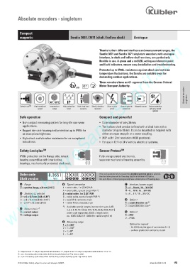
Thanks to their different interfaces and measurement ranges, the
Sendix 3651 and Sendix 3671 singleturn encoders with analogue
interface, in shaft and hollow shaft versions, are particularly
flexible in use. A green and a red LED, acting as reference point
and fault indicators, ensure easy installation and troubleshooting.
Protected up to IP69k, resistance against shock and extreme
temperature fluctuations, the Sendix are suitable even for
demanding outdoor applications.
These encoders have an e1-approval from the German Federal
RoHS
Motor Transport Authority.
Absolute encoders
2/22
-40°... +85°C IP singleturn
Safety-Lock TM High rotational Temperature High protection High shaft load Shock / vibration Short-circuit Reverse polarity Magnetic sensor Surface protection
speed range level capacity resistant proof protection salt spray-tested
optional
Safe operation Compact and powerful
• Non-contact measuring system for long-life non-wear • Outer diameter of only 36 mm.
applications. • The hollow shaft version is fitted with a blind hole with a
• Rugged die-cast-housing and protection up to IP69k for diameter of up to 10 mm. It can be mounted as required with
an exceptional tightness. either a torque stop pin or a stator coupling.
• High shock and vibration resistance for an exceptional • 360° with 12 bit resolution (4096 positions).
robustness. • For use in 12 V or 24 V vehicle electrical systems.
Safety-Lockplus TM Sensor-Protect TM
IP69k protection on the flange side, robust Fully encapsulated electronics,
bearing assemblies with interlocking separate mechanical bearing assembly.
bearings, mechanically protected shaft seal.
Order code 8.3651 . 2 X X X . X X X X If for each parameter of an encoder the underlined preferred option is selected,
then the delivery time will be 10 working days for a maximum of 10 pieces.
Shaft version Type a b c d e f g h Qts. up to 50 pcs. of these types generally have a delivery time of 15 working days.
a Flange d Type of connection f Interface / power supply
2 = synchro flange, ø 36 mm [1.42“] 1 = axial cable, 1 m [3.28‘] PUR 3 = 4 ... 20 mA / 10 ... 30 V DC
A = axial cable, special length PUR *) 4 = 0 ... 10 V / 15 ... 30 V DC
b Shaft (ø x L), with flat 2 = radial cable, 1 m [3.28‘] PUR 5 = 0 ... 5 V / 10 ... 30 V DC
3 = ø 6 x 12.5 mm [0.24 x 0.49“] B = radial cable, special length PUR *)
6 = ø 8 x 12.5 mm [0.32 x 0.49“] 3 = axial M12 connector, 5-pin g Option 1
5 = ø 1/4“ x 12.5 mm [0.49“] 4 = radial M12 connector, 5-pin 1 = count direction cw 2)
*) Available special lengths (connection types A, B): 2 = count direction ccw 3)
c Output circuit 1)
2, 3, 5, 8, 10, 15 m [6.56, 9.84, 16.40, 26.25, 32.80, 49.21‘]
3 = current output order code expansion .XXXX = length in dm h Option 2
4 = voltage output ex.: 8.3651.233A.1311.0030 (for cable length 3 m) 1 = IP67
2 = IP69k
e Measuring range
1 = 1 x 360° Optional on request
2 = 1 x 180° - Ex 2/22 (only for type of connection 3 + 4)
3 = 1 x 90° - surface protection salt spray tested
4 = 1 x 45°
1) Output circuit “3“ only in conjunction with interface “3“, output circuit “4“ only in conjunction with interface “4“ or “5“.
2) cw = Increasing code values when shaft turning clockwise (cw). Top view on shaft.
3) ccw = Increasing code values when shaft turning counterclockwise (ccw). Top view on shaft.
© Fritz Kübler GmbH, subject to errors and changes. 02/2015 www.kuebler.com 155