
Page 158 - Keubler Motion Sensors
P. 158
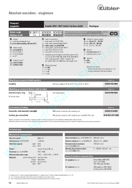
Absolute encoders - singleturn


          Compact
          magnetic                        Sendix 3651 / 3671 (shaft / hollow shaft)  Analogue
         Materials  www.HydroSanatSharif.com
          Order code        8.3671 . X X X X . X X X X      If for each parameter of an encoder the underlined preferred option is selected,
                                                            then the delivery time will be 10 working days for a maximum of 10 pieces.
          Hollow shaft         Type    a b c d    e  f  g h  Qts. up to 50 pcs. of these types generally have a delivery time of 15 working days.
          a     Flange                 d     Type of connection              f     Interface / power supply
           2  = with spring element, long   1  =  axial cable, 1 m [3.28‘] PUR   3  =  4 ... 20 mA / 10 ... 30 V DC
           5  =  with stator coupling, ø 46 mm [1.81“]   A = axial cable, special length PUR *)   4  =  0 ... 10 V / 15 ... 30 V DC
                                        2  =  radial cable, 1 m [3.28‘] PUR   5  =  0 ... 5 V / 10 ... 30 V DC
          b     Hollow shaft            B = radial cable, special length PUR *)
           2  =  ø 6 mm [0.24“]         3  =  axial M12 connector, 5-pin     g   Option 1

           4  =  ø 8 mm [0.32“]         4  =  radial M12 connector, 5-pin    1  =  count direction cw  2)
           6  =  ø 10 mm [0.39“]        *)   Available special lengths (connection types A, B):   2  =  count direction ccw  3)
           3  =  ø 1/4“                      2, 3, 5, 8, 10, 15 m [6.56, 9.84, 16.40, 26.25, 32.80, 49.21‘]
                                             order code expansion .XXXX = length in dm  h     Option 2
          c     Output circuit  1)                                           1  =  IP67
                                             ex.: 8.3671.523A.1311.0030 (for cable length 3 m)
           3  =  current output                                              2  =  IP69k
           4  =  voltage output        e     Measuring range
                                        1  =  1 x 360°                            Optional on request
                                        2  =  1 x 180°                            -  Ex 2/22 (only for type of connection 3 + 4)
                                        3  =  1 x 90°                             -  surface protection salt spray tested
                                        4  =  1 x 45°

         Mounting accessory for shaft encoders                                                     Order no.
         Coupling                                bellows coupling ø 19 mm [0.75“] for shaft 6 mm [0.24“]   8.0000.1102.0606

         Mounting accessory for hollow shaft encoders                                              Order no.
         Cylindrical pin, long                    with fixing thread                             8.0010.4700.0000

                                  6:  >    @  P
         for torque stops

                            0             5


         Connection technology                                                                     Order no.
         Connector, self-assembly (straight)     M12 female connector with coupling nut         8.0000.5116.0000
         Cordset, pre-assembled                  M12 female connector with coupling nut, 2 m [6.56‘] PVC cable   05.00.6081.2211.002M
         Further accessories can be found in the accessories section or in the accessories area of our website at: www.kuebler.com/accessories.
         Additional connectors can be found in the connection technology section or in the connection technology area of our website at: www.kuebler.com/connection_technology.


         Technical data

         Mechanical characteristics
                                                                                           2
         Maximum speed             6000 min -1              Shock resistance acc. to EN 60068-2-27  5000 m/s , 6 ms
         Starting torque at 20°C [68°F]  < 0.06 Nm          Vibration resistance acc. to EN 60068-2-6  300 m/s , 10 ... 2000 Hz
                                                                                          2
                                                                                           2
         Shaft load capacity   radial  40 N                 Permanent shock resistance   1000 m/s , 2 ms
                              axial  20 N                   acc. to EN 60068-2-27
                                                                                                 2
         Weight                    approx. 0.2 kg [7.06 oz]  Vibration (broad-band random)   5 ... 2500 Hz, 100 m/s  - rms
                                                            acc. to EN 60068-2-64
         Protection acc. to EN 60529  IP67 / IP69k
         Working temperature range  -40°C ... +85°C [-40°F ... +185°F]
                                                            General electrical characteristics
                      shaft / hollow shaft  stainless steel
                              flange  aluminium              e1 compliant acc. to     EU guideline 2009/19/EC
                             housing  zinc die-cast                                  (acc. to EN 55025,
                              cable  PUR                                             ISO 11452 and ISO 7637)
                                                            CE compliant acc. to     EMC guideline 2004/108/EC
                                                                                     RoHS guideline 2011/65/EU


         1)  Output circuit “3“ only in conjunction with interface “3“, Output circuit “4“ only in conjunction with interface “4“ or “5“.
         2)   cw = increasing code values when shaft turning clockwise (cw). Top view on shaft.
         3)   ccw = increasing code values when shaft turning counterclockwise (ccw). Top view on shaft.
         156    www.kuebler.com                                                 © Fritz Kübler GmbH, subject to errors and changes. 02/2015