Page 132 - Keubler Motion Sensors
P. 132

Incremental encoders


          Large hollow shaft
          robust, optical                      A02H (hollow shaft)               Push-Pull / RS422 / SinCos
        www.HydroSanatSharif.com
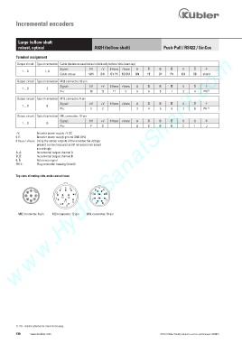
         Terminal assignment
          Output circuit   Type of connection   Cable (isolate unused wires individually before initial start-up)
                               Signal:       0 V   +V   0 Vsens  +Vsens   A      B         0          )
            1 ... D    1, A
                               Cable colour:    WH    BN    GY PK   RD BU    GN    YE    GY    PK    BU    RD    shield
            Output circuit   Type of connection   M23 connector, 12-pin
                               Signal:       0 V   +V   0 Vsens  +Vsens   A      B         0          )
             1 ... D    2
                               Pin:          10    12    11    2    5     6     8    1     3     4   PH  1)
            Output circuit   Type of connection  M12 connector, 8-pin
                               Signal:       0 V   +V   0 Vsens  +Vsens   A      B         0          )
             1 ... D    E
                               Pin:           1    2                3     4     5    6     7     8    PH  1)
            Output circuit   Type of connection  MIL connector, 10-pin
                               Signal:       0 V   +V   0 Vsens  +Vsens   A      B         0          )
             1 ... D    D
                               Pin:           F    D                A     G    B     H     C     I    J
         +V:       Encoder power supply +V DC
         0 V:       Encoder power supply ground GND (0 V)
         0 Vsens / +Vsens:  Using the sensor outputs of the encoder, the voltage
                   present can be measured and if necessary increased
                   accordingly.
         A,  :       Incremental output channel A
         B,  :       Incremental output channel B
         0,  :      Reference signal
         PH ):       Plug connector housing (shield)


         Top view of mating side, male contact base


                              1  9  8              $
                2                               +                                                        $
              3              2                *      %                     )   $                       )   %
              4  8  1          10  12  7         ,                         (  *  %
              5   7         3                 )  -   &                                                (    &
                6               11   6                                      '  &                         '
                               4                (  '
                                  5
          M12 connector, 8-pin  M23 connector, 12-pin  MIL connector, 10-pin


         1)  PH = shield is attached to connector housing.
         130    www.kuebler.com                                                 © Fritz Kübler GmbH, subject to errors and changes. 02/2015
   127   128   129   130   131   132   133   134   135   136   137