
Page 42 - Keubler Motion Sensors
P. 42
Basics
Connection technology Introduction / Cables and connectors
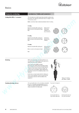
Coding of the M12 x 1 connectors The connectors are coded to guarantee protection against polar-
www.HydroSanatSharif.com
ity reversal. This coding is achieved by means of a peg or a notch
in the contact carrier.
Kübler connectors make a distinction between A, B or D coding.
A-coding
Female connector with coupling nut: Coding notch
Male connector with external thread: Coding peg
Use: CANopen and
8-pin connector
B-coding
Female connector with coupling nut: Coding peg
Male connector with external thread: Coding notch
Use: Profibus
D-coding
Female connector with coupling nut: Coding peg and
Coding notch
Male connector with external thread: Coding peg and
Coding notch
Use: Profinet and
EtherCAT
Shielding With round connectors, care must be taken to con-
nect carefully the shielding braid of the cable to the
shield connection of the connector.
An all-round contact (360°) is optimal.
Good (in practice often sufficient) shielding values
are also reached by connecting the shielding braid
firmly to the electrically conductive housing. Con-
nectors purely out of plastic, without metal sleeve,
providing no contact for the shielding braid, are not
sufficient.
Furthermore, a proper contact with the mating con-
nector is also important, as well as a good contact
of the mating connector with the chassis of the
equipment. ”Allround” shielding
with Kübler cordsets
Counting direction cw/ccw The counting direction of the connectors is indicated Top view of mating side
by cw for a clockwise arrangement and ccw for a
counter-clockwise arrangement. The connector is
always viewed from the mating side. 8 9 1 1 8
7 12 10 2 2 9
7
6 3 3 10 12
11 11 6
5 4 4 5
Counting direction cw Counting direction ccw
(e.g. female connector) (e.g. male connector)
40 www.kuebler.com © Fritz Kübler GmbH, subject to errors and changes. 02/2015