
Page 414 - Keubler Motion Sensors
P. 414
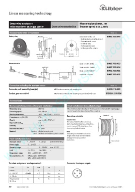
Linear measuring technology


          Draw wire mechanics                                          Measuring length max. 3 m
          with encoder or analogue sensor      Draw wire encoder B75   Traverse speed max. 0.8 m/s
        www.HydroSanatSharif.com
         Accessories for draw wire encoder                                                         Order no.
         Guide pulley                                                  Order code for the set:   8.0000.7000.0045

                                                                       - Guide pulley (anodised aluminium)
                                                                       -  2 x countersunk screws
                                                                         for lateral fixing
                                                                       - 2 x hexagonal screws
                                                                         for fixing on a flat surface


         Extension cable                                               Steel wire 2 m [6.56‘]   8.0000.7000.0033
                                PD[         PD[                        Steel wire 5 m [16.40‘]   8.0000.7000.0034

                                                                       Steel wire 10 m [32.81‘]   8.0000.7000.0035


                                                                           0
                                                                     0    Paraleine 2 m [6.56‘]   8.0000.7000.0032


                                                 /     /
         Connection technology for analogue sensor                                                 Order no.
         Connector, self-assembly (straight)     M12 female connector with coupling nut         8.0000.5116.0000

         Cordset, pre-assembled                  M12 female connector with coupling nut, 2 m [6.56‘] PVC cable   05.00.6081.2211.002M


         Technical data

         Mechanical characteristics (draw wire mechanics)    Electrical characteristics (digital output)
         Measuring range           3000 mm                   The electrical characteristics of the draw wire mechanics with digital output
         Traversing speed          max. 0.8 m/s              can be found in the data sheets of the encoders.
         Working temperature       -40°C ... +80°C [-40°F ... +176°F]                       Drum width
                                                            Operating principle
         Protection acc. to EN 60529     IP65
         Weight                    approx. 500 g [17.67 oz]  Construction
                                                            The core of a draw wire device is a
         Required force F min      3 N
                                                            drum mounted on bearings, onto which
         Linearity                 ±0.35 %                  a wire is wound. Winding takes place
         Repetition accuracy       ±0.15 mm                 via a spring-loaded device.                 Drum diameter
         Material            housing  plastic / zinc die-cast      Note
                               wire  stainless steel ø 0.9 mm, plastic-coated  Exceeding the maximum extension
                                                            length of the draw wire will lead to
                                                            damage to the wire and the
         Electrical characteristics
                                                            mechanics.
         Analogue output     0 ... 10 V DC     4 ... 20 mA   potentiometer 10 k1                   Wire diameter
         Power supply     15 ... 28 V DC    –        –
         Operating range     –         15 ... 28 V DC   max. 48 V DC
         Load             max. 500 1     max. 500 1    –
         Temperature range     -40°C ... +80°C [-40°F ... +176°F]
         CE compliant acc. to      EMC guideline 2004/108/EC
                          RoHS guideline 2011/65/EU

         Terminal assignment (analogue output)              Connector (analogue output)

          Colour         BN       WH       GN
          Pin M12         1        2        3        4               2
          0 ... 10 V DC   +24 V DC   0 V   U out    n.c.           3   1
          4 ... 20 mA    +I        -I      n.c.     n.c.             4
          Potentiometer   Po      Pe        S       n.c.
          10 kOhms

         412    www.kuebler.com                                                 © Fritz Kübler GmbH, subject to errors and changes. 02/2015