
Page 385 - Keubler Motion Sensors
P. 385
Absolute encoders – multiturn
Large hollow shaft
optical / magnetic 9081 (hollow shaft) SSI
www.HydroSanatSharif.com
SET input Output
This input is used for a one-time alignment (zeroing) of the encoder immediately Output Default-function
after installation. A high control pulse (+V) applied to this input for a minimum A1 battery control
of 10 ms will reset the current encoder position to the pre-programmed setpoint
value. The default value is zero.
Notes:
• The SET function should only be implemented when the encoder shaft is at
rest.
• For the duration of the SET pulse the SSI interface does not function and
therefore does not output any valid position values! In order to avoid
malfunctions, no SSI clock pulse should occur during the SET pulse.
• If a cable wire is used to configure the SET input, then for EMC reasons
the wire should not remain open but should if at all possible be tied to 0 V,
provided no SET pulse is triggered!
• The response time of the SET input with +V = 5 ... 30 V DC power supply is 10 ms.
Terminal assignment (SSI Synchronous Serial Interface with 12 pin connector)
Interface Type of connection Features M23 connector Absolute encoders
Signal: 0 V +V C+ C- D+ D- ST VR A1 ) multiturn
SET
2 2
Up/down input Pin: 1 2 3 4 5 6 7 8 9 PH
Cable colour: WH BN GN YE GY PK BU RD BK
+V: Encoder power supply +V DC Top view of mating side, male contact base
0 V: Encoder power supply ground GND (0 V)
C+, C-: Clock signal
D+, D-: Data signal 1 9 8
ST: Set input. The current position becomes defined as position zero. 2
VR: Up/down input. As long as this input (High-Level = +V)is active, decreasing 3 10 12 7
code values are transmitted when shaft turning clockwise. 11 6
A1: Output battery monitoring 4 5
)PH: Plug connector housing (Shield)
M23 connector, 12 pin
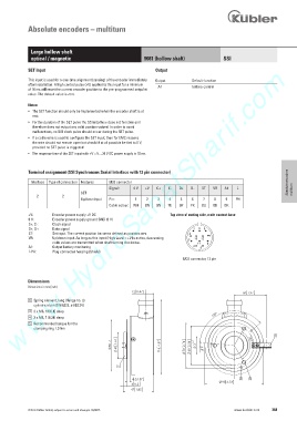
Dimensions
Dimensions in mm [inch]
1 Spring element, long (flange no. 3)
cylindrical pin DIN 6325, ø 6 [0.24]
3 3 x M6, 10 [0.4] deep
4 3 x M4, 7 [0.28] deep
5 Recommended torque for the
clamping ring 1.0 Nm
1
K +
'
© Fritz Kübler GmbH, subject to errors and changes. 02/2015 www.kuebler.com 383