Page 34 - Keubler Motion Sensors
P. 34

Basics


          Encoders                          Installing encoders


         Loading of encoder shaft bearings using   With all spring couplings (shaft coupling, stator cou-  This force does not occur with torque stops for hol-
        www.HydroSanatSharif.com
         coupling forces                   pling, fixing bracket), alignment and axial errors are   low shaft encoders, where the encoder is prevented
                                           converted to a force that corresponds to the spring   from turning also by means of a pin or rod.
                                           constant of the coupling.         Although the encoder is prevented from rotating due
                                           This force has to be absorbed by the encoder shaft   to a rigid interlock, the encoder is still free to move in
                                           bearings. When installing an encoder, this should be   any other direction. This is of course dependent on it
                                           done with as little force as possible, i.e. without any   being mounted in such a way that it has freedom to
                                           unnecessary initial tension on the coupling. If this is   move radially and especially axially (thermal linear
                                           adhered to, then with all Kübler couplings adequate   expansion of the drive shaft!).
                                           tolerance compensation is guaranteed for the whole
                                           service life of the encoder bearings.


         Possible errors in accuracy due to    1. Deviations in accuracy caused by torsion of a spring coupling (in particular shaft couplings)
         couplings                         This deviation in accuracy is defined by the torque   The following applies:
                                           to be transmitted (bearing friction and mass moment   Max. error  max. torque [Ncm]
                                           of inertia) and by the torsional spring constant of the    =
                                                                             (degree)      torsional spring constant [Ncm/Grad]
                                           torque stop.
                                                                             The following table serves to estimate the ratio
                                                                             between such an error and the smallest increment
                                                                             of an encoder:


                                           Relationship between the resolution of an encoder in bit and the smallest increment in angular degrees:
                                                     binary    10 bit   11 bit   12 bit   13 bit   14 bit   17 bit
                                            Resolution
                                                     ppr       1024    2048    4096    8192    16384   131072
                                                     degrees   0.352   0.176   0.088   0.044   0.022   0.0028
                                            Increment   degrees:min:sec  0:21:06   0:10:33   0:05:16   0:02:38   0:01:19   0:00:10
                                                     sec       1266    633     316     158     79      10

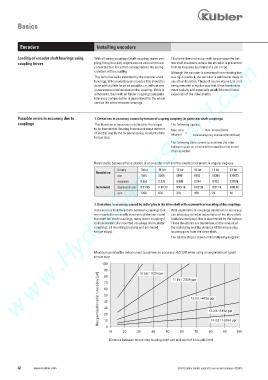
                                           2. Deviations in accuracy caused by radial play in the drive shaft with asymmetrical mounting of the couplings
                                           Here one has to differentiate between couplings that   With asymmetrical couplings deviations in accuracy
                                           are mounted in an axially symmetrical manner round   can arise due to radial movements of the drive shaft
                                           the shaft (all shaft couplings, many stator couplings)   (radial runout/play); this is determined by the system.
                                           and asymmetrically mounted couplings (many stator   These deviations are dependent on the amount of
                                           couplings, all mounting brackets and pin-based   the radial play and the distance of the torque stop
                                           torque stops).                    locating point from the drive shaft.
                                                                             The relationship is shown in the following diagram:


                                           Maximum permissible radial runout to achieve an accuracy >1/2 LSB when using an asymmetrical 1 point
                                           torque stop
                                              100
                                               90              10 bit / 1024 ppr

                                            ]  80
                                            m                                 11 bit / 2048 ppr
                                            µ
                                            [  70

                                            l
                                            e
                                            i
                                            p  60
                                            S
                                            -
                                            /
                                            g  50
                                            a
                                            l                                         12 bit / 4096 ppr
                                            h Max. permissible radial runout/play [µm]
                                            c  40
                                            s
                                            l
                                            a
                                            i
                                            d  30
                                            a
                                            R                                                 13 bit / 8192 ppr

                                            .  20
                                            l
                                            u
                                            z
                                            .  10                                              14 bit / 16384 ppr
                                            x
                                            a
                                            M   0
                                                 10     20    30    40     50    60    70     80    90    100
                                                 Abstand zwischen Drehmomentstützen-Fixpunkt und Antriebsachsen-Mittelpunkt [mm]
                                                  Distance between torque stop locating point and mid-point of drive axle [mm]
         32     www.kuebler.com                                                 © Fritz Kübler GmbH, subject to errors and changes. 02/2015
   29   30   31   32   33   34   35   36   37   38   39