
Page 31 - Keubler Motion Sensors
P. 31
Basics
Encoders Absolute encoders
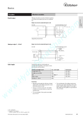
Parallel output This type of transfer is very fast. All bits of a position
www.HydroSanatSharif.com
are transferred simultaneously each via a separate
line.
Output circuit and recommended input circuit Product overview
encoder recommended input circuit Basics
+V
Integrated push-pull driver
Analogue output 4 ... 20 mA Output circuit and recommended input circuit
encoder recommended input circuit
+
voltage
- supply
+U B
10 ... 30 V DC
0 V
Encoder supply
+
D/A
con- PLC
verter - +
-
Cable lengths The following maximum cable lengths are
recommended, depending on the output circuitry
and any noise sources present
Interface and output circuit max. cable length Connected to
Parallel CMOS / TTL 2 m SPS / IPC 1)
Parallel push-pull (HTL) 100 m SPS / IPC 1)
2)
SSI up to 1000 m SPS / IPC 1)
RS422 / RS485 1000 m SPS / IPC 1)
Analogue 4 ... 20 mA 200 m
Annotations:
• Depending on the application the max. allowed • The core diameter of the voltage supply cores
cable length can be shorter, especially in areas should be large enough depending on the cable
with strong electrical noise length, that the voltage supply of the encoder is
• Always use shielded cables; the cable shield high enough and the signals do not go below the
should be connected at both the encoder and minimum levels!
controller ends.
• The core diameter of the signal cores should
be * 0.14 mm 2
1) IPC = Industrial PC
2) Depends on clock frequency:
at 100 kHz L max approx. 250 m; at f = 250 kHz L max approx. 50 m
© Fritz Kübler GmbH, subject to errors and changes. 02/2015 www.kuebler.com 29