
Page 32 - Keubler Motion Sensors
P. 32
Basics
Encoders Installing encoders
Encoders shafts and in turn their bearings are sub- Not making use of a coupling but instead rigid-
www.HydroSanatSharif.com
jected to loads for a variety of reasons: ly mounting the shaft and the encoder housing
• Installation tolerances when mounting the generally leads to unacceptably high loads on the
encoders (radial and angular displacement) bearings; the ensuing wear will cause the encoder
to fail prematurely.
• Thermal changes, e.g. linear expansion of the
drive shaft In order to avoid permanent damage of the encoder,
certain bearing loads should not be exceeded. If
• Effects of wear, e.g. radial runout of the drive
shaft or vibrations hollow shaft encoders are correctly installed and the
torque stops or stator couplings that are available
These load factors have a direct effect on the life from Kübler are used, then no problems should oc-
expectancy of the shaft bearings and on the quality cur. For solid shaft encoders the maximum permitted
of the signal.
axial and radial loads are shown in the appropriate
Facilities must therefore be provided during technical data.
installation to compensate for these forces. For
encoders having a solid shaft this is generally done
by using shaft couplings between the drive shaft and
the encoder shaft. The solution with hollow shaft
encoders is to use stator couplings, fixing brackets
or torque stops between the encoder flange and the
mounting surface.
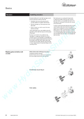
Mounting options for hollow shaft Hollow shaft encoder with torque stop and pin
encoders (easiest and fastest mounting)
Standard hollow shaft encoders are equipped with
the torque stop (cylindrical pin not supplied).
Extended torque stop and long pin
Stator coupling
30 www.kuebler.com © Fritz Kübler GmbH, subject to errors and changes. 02/2015