
Page 292 - Keubler Motion Sensors
P. 292
Absolute encoders – multiturn
Standard
mechanical multiturn, optical Sendix 5863 / 5883 (shaft / hollow shaft) SSI / BiSS
www.HydroSanatSharif.com
Status output and LED DIR input
Output driver open collector, internal pull up A HIGH signal switches the direction of rotation from the default cw to ccw.
resistor 22 kOhm This function can also be factory-programmed to be inverted. If DIR is changed
Permissible load max. 20 mA when the device is already switched on, then this will be interpreted as an
error. The LED will come ON and the status output will switch to LOW.
Signal level HIGH: +V / LOW: < 1 V
Active LOW
The optional LED (red) and the status output serve to display various alarm or Power-ON time
error messages. In normal operation the LED is OFF and the status output is After Power-ON the encoder requires a time of approx. 150 ms before valid data
HIGH (open collector with int. pull up 22 kOhm). can be read.
An active status output (LOW) displays:
– sensor error, singleturn or multiturn (soiling, glass breakage etc.)
– LED fault (failure or ageing)
– over- or under-temperature
In the SSI mode, the fault indication can only be reset by switching off the
power-supply to the device.
Terminal assignment
Interface Type of connection Features Cable (isolate unused wires individually before initial start-up)
Signal: 0 V +V C+ C- D+ D- SET DIR Stat N/C N/C N/C )
1, 2 1, 2, A, B, E, F SET, DIR, Status
Cable colour: WH BN GN YE GY PK BU RD BK - - - shield
Interface Type of connection Features M23 connector
Signal: 0 V +V C+ C- D+ D- SET DIR Stat N/C N/C N/C )
1, 2 3, 4 SET, DIR, Status
Pin: 1 2 3 4 5 6 7 8 9 10 11 12 PH
Interface Type of connection Features Cable (isolate unused wires individually before initial start-up)
SET, DIR, Status Signal: 0 V +V C+ C- D+ D- SET DIR Stat N/C 0 Vsens +Vsens )
5 1, 2, A, B, E, F
sensor output Cable colour: WH BN GN YE GY PK BU RD BK - GY-PK RD-BU shield
Interface Type of connection Features M23 connector
SET, DIR, Status Signal: 0 V +V C+ C- D+ D- SET DIR Stat N/C 0 Vsens +Vsens )
5 3, 4
sensor output Pin: 1 2 3 4 5 6 7 8 9 10 11 12 PH
Interface Type of connection Features Cable (isolate unused wires individually before initial start-up)
SET, DIR, SinCos Signal: 0 V +V C+ C- D+ D- SET DIR A B )
3, 4, 7, 8 1, 2, A, B, E, F
or incr. RS422 Cable colour: WH BN GN YE GY PK BU RD BK VT GY-PK RD-BU shield
Interface Type of connection Features M23 connector
SET, DIR, SinCos Signal: 0 V +V C+ C- D+ D- SET DIR A B )
3, 4, 7, 8 3, 4
or incr. RS422 Pin: 1 2 3 4 5 6 7 8 9 10 11 12 PH
Interface Type of connection Features Cable (isolate unused wires individually before initial start-up)
SinCos o. incr. RS422 Signal: 0 V +V C+ C- D+ D- A B 0 Vsens +Vsens )
6, 9 1, 2, A, B, E, F
sensor output Cable colour: WH BN GN YE GY PK BU RD BK VT GY-PK RD-BU shield
Interface Type of connection Features M23 connector
SinCos o. incr. RS422 Signal: 0 V +V C+ C- D+ D- A B 0 Vsens +Vsens )
6, 9 3, 4
sensor output Pin: 1 2 3 4 5 6 7 8 9 10 11 12 PH
Interface Type of connection Features M12 connector
Signal: 0 V +V C+ C- D+ D- SET DIR )
1, 2 5, 6 SET, DIR
Pin: 1 2 3 4 5 6 7 8 PH
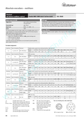
+V: Encoder power supply +V DC SET: SET input. The current position Top view of mating side, male contact base
0 V: Encoder power supply ground GND (0 V) becomes defined as position zero.
0 Vsens / +Vsens: Using the sensor outputs of the encoder, DIR: Direction input: If this input is 9
the voltage present can be measured active, output values are counted 3 2 1 8
and if necessary increased accordingly. backwards (decrease) when the 4 8 1 2 7
C+, C-: Clock signal shaft is turning clockwise. 5 7 3 10 12
D+, D-: Data signal Stat: Status output 6 11 6
A, : Incremental output channel A (cosine) PH ): Plug connector housing (shield) 4 5
B, : Incremental output channel B (sine)
M12 connector, 8-pin M23 connector, 12-pin
290 www.kuebler.com © Fritz Kübler GmbH, subject to errors and changes. 02/2015