
Page 227 - Keubler Motion Sensors
P. 227
Absolute encoders - singleturn
Standard
optical Sendix 5858 / 5878 (shaft / hollow shaft) PROFINET IO
www.HydroSanatSharif.com
General information about PROFINET IO PROFINET IO
The PROFINET encoder implements the encoder profile 4.1. (according to the The complete encoder profile according to profile encoder version 4.1 as well as
specification Encoder Version 4.1 Dec 2008“) the identification & maintenance functionality version 1.16 has been implemen-
It permits scaling and preset values, as well as many other additional parame- ted. IM blocks 0, 1, 2, 3 and 4 are supported.
ters to be programmed via the PROFINET bus. The Media Redundancy Protokoll is implemented here.
When switching on, all parameters are loaded from an EEPROM, where they Basically, the advantage of MRP is that the functionality of the components,
were saved previously to protect them against power-failure, or taken over by which are wired in a ring structure, is maintained in case of a failure or of a
the controller in the start-up phase. breakage of the wires in any location.
Position, speed and many other states of the encoder can be transmitted.
Absolute encoders
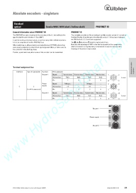
Terminal assignment bus
Interface Type of connection Function M12 connector singleturn
Bus port 1 Signal: Transmit data+ Receive data+ Transmit data - Receive data - 1 2 4
Abbreviation: TxD+ RxD+ TxD- RxD- D coded
Pin: 1 2 3 4 4 3
Power Signal: Voltage + – Voltage – – 4 3
1
supply
C 2 Abbreviation: + V – 0 V –
(3 x M12 connector) Pin: 1 2 3 4 1 2
Bus port 2 Signal: Transmit data+ Receive data+ Transmit data - Receive data - 1 2 4
Abbreviation: TxD+ RxD+ TxD- RxD- D coded
Pin: 1 2 3 4 4 3
Bus port 1
Power supply
Bus port 2
© Fritz Kübler GmbH, subject to errors and changes. 02/2015 www.kuebler.com 225