
Page 222 - Keubler Motion Sensors
P. 222
Absolute encoders - singleturn
Standard
optical Sendix 5858 / 5878 (shaft / hollow shaft) EtherCAT
www.HydroSanatSharif.com
General information about CoE (CAN over EtherNet) CANopen encoder profile 3.2.10 CoE (CAN over EtherNet)
The EtherCAT encoders support the CANopen communication profile according The following parameters are programmable:
to DS301. In addition device-specific profiles like the encoder profile DS406 are • Position update time of 62.5 µs.
available. • EtherCAT certificate of conformity.
Scaling, preset values, limit switch values and many other parameters can be • Speed with sign.
programmed via the EtherCAT bus. • Four units for speed calculation: steps/sec, steps/100 ms, steps/10 ms,
When switching the device on, all parameters are loaded from an EEPROM, rotation/min.
where they were saved previously to protect them against power-failure. • Time stamp as system time at the point in time when the position is read out.
• Two working area state registers.
The following output values may be combined as PDO (PDO mapping): position, • Along with the scaled position, the raw data – position as process value – is
speed, temperature values and working area state as well as other process also mappable.
values. • Dynamic mapping.
• Gating time: setting of the time interval, via which the speed value can be
interpolated.
• Sensor temperature in degrees Celsius.
• Comprehensive plausibility test when downloading parameters to the
encoder.
• Alarm and warning messages.
• User interface with visual display of bus and fault status – 4 LEDs.
• Extended error management for position sensing with integrated
temperature control.
• Implementation of the latest CANopen profile 3.2.10 from the
18th February 2011.
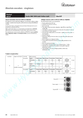
Terminal assignment bus
Interface Type of connection Function M12 connector
Bus port IN Signal: Transmit data+ Receive data+ Transmit data - Receive data - 1 2 4
Abbreviation: TxD+ RxD+ TxD- RxD- D coded
Pin: 1 2 3 4 4 3
Power Signal: Voltage + – Voltage – – 4 3
1
supply
B 2 Abbreviation: + V – 0 V –
(3 x M12 connector) Pin: 1 2 3 4 1 2
Bus port OUT Signal: Transmit data+ Receive data+ Transmit data - Receive data - 1 2 4
Abbreviation: TxD+ RxD+ TxD- RxD- D coded
Pin: 1 2 3 4 4 3
Bus port IN
Power supply
Bus port OUT
220 www.kuebler.com © Fritz Kübler GmbH, subject to errors and changes. 02/2015