
Page 214 - Keubler Motion Sensors
P. 214
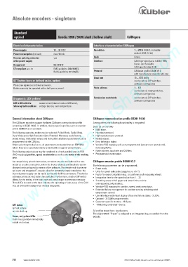
Absolute encoders - singleturn


          Standard
          optical                     Sendix 5858 / 5878 (shaft / hollow shaft)  CANopen
        www.HydroSanatSharif.com
         Electrical characteristics                          Interface characteristics CANopen
         Power supply              10 ... 30 V DC            Resolution               1 ... 65536 (16 bit), scaleable
         Power consumption (no load)      max. 90 mA                                  default: 8192 (13 bit)
         Reverse polarity protection        yes                 Code                  binary
         of the power supply                                 Interface                CAN high-speed acc. to ISO 11898,
         UL approval                file 224618                                        Basic- and Full-CAN
                                                                                      CAN specification 2.0 B
         CE compliant acc. to        EMC guideline 2004/108/EC
                                   RoHS guideline 2011/65/EU  Protocol                CANopen profile DS406 V3.2
                                                                                      with manufacturer-specific add-ons
                                                             Baud rate                10 ... 1000 kbit/s
         SET button (zero or defined value, option)                                    can be set via DIP switches,
                                                                                      software configurable
         Protection against accidental activation.
         Button can only be operated with a ball-pen or pencil.   Node address        1 ... 127
                                                                                      can be set via rotary switches,
                                                                                      software configurable
         Diagnostic LED (yellow)                             Termination switchable      can be set via DIP switches,
                                                                                      software configurable
         LED is ON with the    sensor error (internal code or LED error),
         following fault conditions   voltage too low, over-temperature


         General information about CANopen                  CANopen communication profile DS301 V4.02
         The CANopen encoders support the latest CANopen communication profile   Among others, the following functionality is integrated.
         according to DS301 V4.02 . In addition, device specific profiles such as encoder   Class C2 functionality
         profile DS406 V3.2 are available.                   •   NMT slave.
         The following operating modes may be selected: Polled Mode, Cyclic Mode,   •   Heartbeat protocol.
         Sync Mode and a High Resolution Sync Protokoll. Moreover, scale factors,   •   High resolution sync protocol.
         preset values, limit switch values and many other additional parameters can be   •  Identity object.
         programmed via the CAN bus.                        •   Error behaviour object.
         When switching the device on, all parameters are loaded from an EEPROM,   •   Variable PDO mapping self-start programmable (power on to operational),
         where they were saved previously to protect them against power-failure.    3 Sending PDO’s.
         The following output values may be combined in a freely variable way as PDO   •   Node address, baud rate and CANbus.
         (PDO mapping): position, speed, acceleration as well as the status of the working   •  Programmable termination.
         area.
         As competitively priced alternatives, encoders are also available with a con-  CANopen encoder profile DS406 V3.2
         nector or a cable connection, where the device address and baud rate can be   The following parameters can be programmed:
         changed and configured by means of the software. The models with bus termi-  •   Event mode.
         nal cover and integrated T-coupler allow for extremely simple installation: the   •   Units for speed selectable (steps/sec or min ).
                                                                                        -1
         bus and power supply can be easily connected via M12 connectors. The device   •   Factor for speed calculation (e.g. circumference of measuring wheel).
         address can be set via 2 rotary hex switches. Furthermore, another DIP switch   •   Integration time for the speed value from 1 ... 32.
         allows for the setting of the baud rate and switching on a termination resistor.   •   2 working areas with 2 upper and lower limits and the
         Three LEDs located on the back indicate the operating or fault status of the CAN     corresponding output states.
         bus, as well as the status of an internal diagnostic.   •   Variable PDO mapping for position, speed, work area status.
                                                            •   Extended failure management for position sensing with integrated
                                                              temperature control.
                                                            •   User interface with visual display of bus and failure status - 3 LED’s.
                                                            •   Optional - 32 CAMs programmable.
                                                            •   Customer-specific memory - 16 Bytes.
         SET button                                         •   “Watchdog controlled” device.
         for fast, simple
         on-site start-up                                   All profiles stated here: key-features
                                                            The object 6003h “Preset” is assigned to an integrated key, accessible from the
         Green, red, yellow LEDs                            outside.
         Fault-free operation immediately
         visible on the bus.


         212    www.kuebler.com                                                 © Fritz Kübler GmbH, subject to errors and changes. 02/2015