Page 209 - Keubler Motion Sensors
P. 209

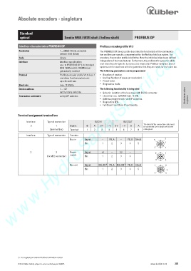
Absolute encoders - singleturn


             Standard
             optical                     Sendix 5858 / 5878 (shaft / hollow shaft)   PROFIBUS DP
        www.HydroSanatSharif.com
             Interface characteristics PROFIBUS DP             Profibus encoder profile V1.1
             Resolution               1 ... 65536 (16 bit), scaleable     The PROFIBUS DP device profile describes the functionality of the communica-
                                      default: 8192 (13 bit)   tion and the user-specific component within the Profibus field bus system. For
             Code                     binary                   encoders, the encoder profile is definitive. Here the individual objects are defined
                                                               independent of the manufacturer. Furthermore, the profiles offer space for additi-
             Interface                interface specification
                                      acc. to PROFIBUS DP 2.0 / standard    onal manufacturer-specific functions; this means that Profibus-compliant device
                                      (DIN 19245 part 3) / RS485 driver    systems can be used now with the guarantee that they are ready for the future too.
                                      galvanically isolated    The following parameters can be programmed
             Protocol                 Profibus encoder profile V1.1 class 1    •   Direction of rotation.
                                      and class 2 with manufacturer-   •   Scaling (Number of steps per revolution ).
                                      specific add-ons          •   Preset value.
             Baud rate                max. 12 Mbit/s           •   Diagnostics mode.
             Device address           1 ... 127                The following functionality is integrated
                                      set by rotary switches   •   Galvanic isolation of the bus stage with DC/DC converter  .
             Termination switchable    set by DIP switches     •   Line driver acc. to RS485 max. 12 MB.            Absolute encoders
                                                               •   Address programmable via DIP switches.             singleturn
                                                               •   Diagnostics LED.
                                                               •   Full Class 1 and Class 2 functionality.


            Terminal assignment terminal box

                  Interface    Type of connection                     BUS IN                      BUS OUT
                                                                                          The shield of the connection cable must
                     3              1        Signal:    B    A    0 V    + V    0 V    + V    B    A
                                                                                          be connected over a large area via the

                                (terminal box)   Terminal:    1    2    3    4    5    6    7    8   cable gland.
                  Interface    Type of connection    Function
                                             Bus in   Signal:    –    PB_A    –    PB_B   Shield       5  2

                                                      Pin:       1    2     3     4    5                1
                                                                                                 3      4
                    3               2        Power    Signal:    +V     –    0 V    –             2     1
                                             supply
                              (3 x M12 connector)      Pin:      1    2     3     4
                                                                                                  3     4
                                                                   1)
                                                                               1)
                                             Bus out   Signal:    BUS_VDC     PB_A   BUS_GND      PB_B   Shield       1  2

                                                      Pin:       1    2     3     4    5                 3
                                                                                                 4      5


            1)   For supplying an external Profibus termination resistor.
            © Fritz Kübler GmbH, subject to errors and changes. 02/2015                        www.kuebler.com  207
   204   205   206   207   208   209   210   211   212   213   214