Page 84 - Keubler Motion Sensors
P. 84

Incremental encoders


          Standard
          sine wave output, with zero pulse, optical  5804 / 5824 (shaft / hollow shaft)  SinCos
        www.HydroSanatSharif.com
         Terminal assignment
            Output circuit   Type of connection   Cable (isolate unused wires individually before initial start-up)
                                                              2)
                                                                    2)
                      5804:   1, 2   Signal:    0 V   +V   0 Vsens     +Vsens     A      B       0       )
              1, 2
                      5824:   1      Cable colour:   WH 0.5 mm 2   BN 0.5 mm 2    WH   BN    GN    YE    GY    PK    BU    RD    shield
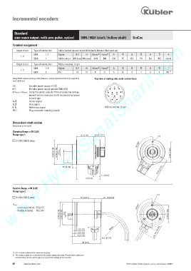
            Output circuit   Type of connection   M23 connector, 12-pin
                                                                    2)
                                                              2)
                      5804:   3, 5   Signal:    0 V   +V   0 Vsens     +Vsens     A      B       0       )
              1, 2
                      5824:   2      Pin:        10   12    11    2     5    6     8     1    3     4    PH  1)
         Using RS422 outputs and long cable distances, a wave impedance has to be applied at       Top view of mating side, male contact base
         each cable end.
         +V:       Encoder power supply +V DC                         1  9  8
         0 V:      Encoder power supply ground GND (0 V)            2
         0 Vsens / +Vsens:  Using the sensor outputs of the encoder, the voltage       7
                   present can be measured and if necessary increased       3  10  12
                   accordingly.                                       4  11  6
         A,  :     Cosine signal                                         5
         B,  :     Sine signal
         0,  :     Reference signal                               M23 connector, 12-pin
         PH ):     Plug connector housing (shield)


         Dimensions shaft version
         Dimensions in mm [inch]

         Clamping flange, ø 58 [2.28]
         Flange type 1                                >    @
                                                                   >    @
         1   3 x M3, 5 [0.2] deep
                                                                          [   ƒ        [   ƒ
                                   >    @     >    @  I   '   >    @     >    @  I   '


                                           ; L          ;
                                           >    @       >    @

                                                                   >    @       >    @
                                                         >   @        >   @


         Synchro flange, ø 58 [2.28]
         Flange type 2
                                                                                                      1
         1   3 x M4, 5 [0.2] deep                  5 1 2[   0 .  ] 1  ca. 16  6 . 0 [    ] 3

          R min .:
            -  securely installed:  55 [2.17]                                         3x120°
            -  flexibly installed:   70 [2.76]
                                      58 [2.28]   [1.97]  D                                               42 [1.65]
                                        50
                                             X L

                                                                      m  i  n  .                   [0.63]
                                                 3 0[   1 .  ] 2      R
                                                 3 0[   1 .  ] 2
                                                    1 . 0 [   4  ] 6                             ca. 16
                                                                1    5 . 0 [   5 , 4  ] 7
                                                    6   ] 6 . 2 [   6


         1)  PH = shield is attached to connector housing.
         2)  The sensor cables are connected to the power supply internally. If long feeder cables are
            involved they can be used to adjust or control the voltage at the encoder.
         82     www.kuebler.com                                                 © Fritz Kübler GmbH, subject to errors and changes. 02/2015
   79   80   81   82   83   84   85   86   87   88   89