
Page 67 - Keubler Motion Sensors
P. 67
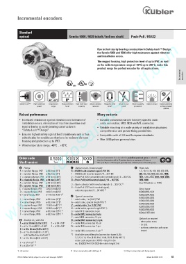
Incremental encoders


             Standard
             optical                         Sendix 5000 / 5020 (shaft / hollow shaft)  Push-Pull / RS422
        www.HydroSanatSharif.com

                                                               Due to their sturdy bearing construction in Safety-Lock™ Design,
                                                               the Sendix 5000 and 5020 offer high resistance against vibration
                                                               and installation errors.
                                                               The rugged housing, high protection level of up to IP67, as well
                                                               as the wide temperature range of -40°C up to +85°C, make this
                                                               product range the perfect encoder for all applications.
                                                                                                                    Incremental  encoders


                                                          RoHS
                                                2/22


                                -40°... +85°C  IP
              Safety-Lock TM  High rotational  Temperature  High protection   High shaft load  Shock / vibration  Magnetic field  Short-circuit  Reverse polarity  Optical sensor  Surface protection
                         speed    range    level   capacity  resistant  proof  proof   protection       salt spray-tested
                                                                                                          optional
             Robust performance                                Many variants
             •   Increased resistance against vibrations and tolerance of   •   Suitable connection variant for every specific case:
               installation errors, elimination of machine downtime and      cable connection, M12, M23 and MIL connector.
               repairs thanks to sturdy bearing construction in    •   Reliable mounting in a wide variety of installation situations:
               “Safety-Lock TM  Design”.                         comprehensive and proven fixing possibilities.
             •   Ensures highest safety against field breakdowns and is thus   •   Compatible with all US and European standards.
               suitable also for outside use thanks to its resistant die-cast
               housing and protection up to IP67.              •   Max. 5000 pulses per revolution.
             •   Wide temperature range, -40°C ... +85°C.


             Order code          8.5000 . X X X X . XXXX       If for each parameter of an encoder the underlined preferred option is selected,
                                                               then the delivery time will be 10 working days for a maximum of 10 pieces.
             Shaft version         Type     a b c d      e     Qts. up to 50 pcs. of these types generally have a delivery time of 15 working days.
              a     Flange                     c     Output circuit / power supply      e     Pulse rate
              5  =  synchro flange, IP67    ø 50.8 mm [2“]   4  =  RS422 (with inverted signal) / 5 V DC         1, 5, 10, 12, 36, 100, 200, 250, 256,
              6  =  synchro flange, IP65   ø 50.8 mm [2“]   1  =  RS422 (with inverted signal) / 5 ... 30 V DC        360, 400, 500, 512, 600, 800, 1000,
              7  =  clamping flange, IP67   ø 58 mm [2.28“]   2  =  Push-Pull (7272 compatible with inverted signal) / 5 ... 30 V DC        1024, 1200, 2000, 2048, 2500, 3600,
              8  =  clamping flange, IP65  ø 58 mm [2.28“]   5  =  Push-Pull (with inverted signal) / 10 ... 30 V DC        4096, 5000
              A  =  synchro flange, IP67    ø 58 mm [2.28“]                     1)            (e.g. 100 pulses => 0100)
              B  =  synchro flange, IP65    ø 58 mm [2.28“]        3  =  Open collector (with inverted signal) / 5 ... 30 V DC
                                               8  =  Push-Pull (7272 with inverted signal),
             C  =  square flange, IP67     63.5 mm [2.5“]            1)                       Stock types
              D  =  square flange, IP65    63.5 mm [2.5“]        without capacitor / 5 ... 30 V DC         8.5000.8354.1024
              G = euro flange, IP67    ø 115 mm [4.53“]  2)                                   8.5000.8354.5000
                                               d     Type of connection
              1  =  servo flange, IP67    ø 50.8 mm [2“]  1)   1  =  axial cable, 1 m [3.28‘] PVC        8.5000.8358.0200
                                                                                             8.5000.8358.0360
              2  =  servo flange, IP65    ø 50.8 mm [2“]  1)   A  =  axial cable, special length PVC *)        8.5000.8358.0500
              3  =  square flange, IP67     50.8 mm [2“]  1)   2  =  radial cable, 1 m [3.28‘] PVC        8.5000.8358.1000
              4  =  square flange, IP65     50.8 mm [2“]  1)   B  =  radial cable, special length PVC *)        8.5000.8358.5000
              E  = servo flange, IP67    ø 63.5 mm [2.5“]  1)   3  =  axial M12 connector, 8-pin        8.5000.B157.1024
              F  = servo flange, IP65   ø 63.5 mm [2.5“]  1)   4  =  radial M12 connector, 8-pin
                                               7  = axial M23 connector, 12-pin
              b     Shaft (ø x L), with flat    8  =  radial M23 connector, 12-pin            Optional on request
              1  =  ø 6 x 10 mm [0.24 x 0.39“]   2  =  ø 1/4 x 5/8“   Y  =  radial MIL connector, 10-pin        -  other pulse rates
                                                                                             -  Ex 2/22
              6  =  ø 8 x 15 mm [0.32  x 0.59“]   4  =  ø 3/8 x 5/8“   W =  radial MIL connector, 7-pin        -  surface protection salt spray
              3  =  ø 10 x 20 mm [0.39 x 0.79“]   9  =  radial  MIL connector, 6-pin  1)          tested

              B = ø 11 x 33 mm [0.43  x 1.30“],
                   with feather key shaft slot  3)   *)    Available special lengths (connection types A, B):
              5  =  ø 12 x 20 mm [0.47 x 0.79“]        2, 3, 5, 8, 10, 15 m [6.56, 9.84, 16.40, 26.25, 32.80, 49.21‘]
                                                    order code expansion .XXXX = length in dm
              7  = ø 1/4 x 7/8“  1)                 ex.: 8.5000.814A.1024.0030 (for cable length 3 m)
              8  = ø 3/8 x 7/8“  1)
            1)  US version.                                  2)   Only in conjunction with shaft type B.                  3)   Only in conjunction with flange type G.
            © Fritz Kübler GmbH, subject to errors and changes. 02/2015                        www.kuebler.com  65