
Page 22 - Keubler Motion Sensors
P. 22
Basics
Encoders Incremental encoders
Processing of the signals The sine wave signals are then processed in a spe- The signals are therefore pre-processed accordingly
www.HydroSanatSharif.com
(optical, incremental encoders) cially designed electronic circuitry. Most controllers in the encoder and made available using various
require square-wave signals on their input. output circuits depending on the application.
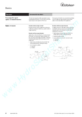
Number of channels Encoders with one output channel: Encoders with three output channels:
Encoders with one output channel are used where In addition to the two channels A and B a zero pulse
no direction sensing is needed, e.g. speed control or is available, which occurs once per revolution and
length measuring. is usually used for the reference run (zero point
calibration) of a machine.
Encoders with two output channels: • Shaft turning clockwise, top-view of shaft / for
hollow shaft encoders, viewing the flange
Applications, where the direction of rotation should
be sensed, e.g. positioning, require encoders with • Inverted signals available
two channels A and B being shifted 90° out of phase. • 0 pulse is linked to AND with channel A and B
By detecting the phase shift, the direction can be t r = rise time
determined. t f = fall time
• Shaft turning clockwise, top-view of shaft / for
hollow shaft encoders, viewing the flange
• Inverted signals available
t r = rise time
t f = fall time
20 www.kuebler.com © Fritz Kübler GmbH, subject to errors and changes. 02/2015