
Page 24 - Keubler Motion Sensors
P. 24
Basics
Encoders Incremental encoders
Sensor outputs With long cable runs, the inherent resistance of the Using the sensor outputs of the encoder, the voltage
www.HydroSanatSharif.com
cables can lead to a situation where insufficient present can be measured and if necessary increased
supply voltage is available to the encoder. accordingly.
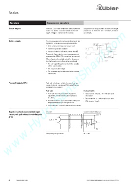
Digital outputs The sine wave signal from the optical system is first
digitised to have square wave signals available.
• Shaft turning clockwise, top view of shaft
• Inverted signals are available
• 0 pulse is linked to AND with channel A and B
To transmit the signals there are two possible out-
puts available. RS422 (TTL compatible) or push-pull.
When choosing the suitable output for the applica-
tion the following points have to be considered:
• The corresponding unit / controller the encoder
will be connected to
• The required cable length
• The sensitivity against electrical noise or other
interference
Push-pull outputs (HTL) Push-pull outputs are suitable for count interface
cards, electronic counters or PLC inputs. They are
available in two versions:
Push-pull: Push-pull (7272):
• Push-pull with integrated wave impedance • Universal line driver 5 ...... 30 V with low-level
adjustment, recommended cable impedance (max 0.5 V)
40 ... 150 1 • Recommended for cable lengths up to 30 m
• Recommended for long cable lengths, high pulse • With inverted signals
frequencies and output voltages to 30 V
• With or without inverted (complementary) signals
Output circuit and recommended input encoder recommended input circuit
circuit push-pull without inverted signals +V
(HTL)
A, B, 0
RL +V
2
0 V
integrated push-pull driver RL = 1 k1
22 www.kuebler.com © Fritz Kübler GmbH, subject to errors and changes. 02/2015