
Page 25 - Keubler Motion Sensors
P. 25
Basics
Encoders Incremental encoders
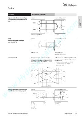
Output circuit and recommended input encoder recommended input circuit
www.HydroSanatSharif.com
circuit push-pull with inverted signals
+V
(HTL)
A, B, 0 Product overview
RL Basics
A, B, 0 0 V
Integrated push-pull driver RL = 1 k1
RS422 encoder recommended input circuit
Output circuit and recommended
input circuit (TTL)
RS422 line driver RS422 line receiver
e.g. AM26 C 32 / Z = 120 1
Sine wave outputs The sine wave signals are available as voltage Further they are very suitable for digital drives with
signals. They can be further processed in the eva- a very slow movement, e.g. for grinding machines or
luation electronics. Due to the interpolation of the lifts and elevators.
two signals, which are 90° out of phase, a very high • Shaft turning clockwise, top view of shaft
resolution can be achieved.
• 0 pulse is generated once per turn
(only with 5804 / 5824)
COS
1 Vpp
SIN
1 Vpp
1 Vpp
Output circuit and recommended input encoder recommended input circuit
circuit for sine wave voltage signals
+V
–V
R a = 10 1 Z = 120 1 operation amplifier:
C 1 = 150 pF U 1 = U 0 e.g. MC33074
C 2 = 10 pF
R 1 = 10 k1
R 2 = 33 k1
U 0 = 2.5 V ±0.5 V
© Fritz Kübler GmbH, subject to errors and changes. 02/2015 www.kuebler.com 23