Page 126 - Keubler Motion Sensors
P. 126

Incremental encoders


          Large hollow shaft
          optical                              A020 (hollow shaft)               Push-Pull / RS422 / SinCos
        www.HydroSanatSharif.com
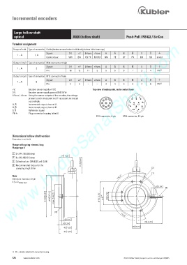
         Terminal assignment
          Output circuit   Type of connection   Cable (isolate unused wires individually before initial start-up)
                               Signal:       0 V   +V   0 Vsens  +Vsens   A      B         0          )
            1 ... A    1, A
                               Cable colour:    WH    BN    GY PK   RD BU    GN    YE    GY    PK    BU    RD    shield
            Output circuit   Type of connection   M23 connector, 12 pin
                               Signal:       0 V   +V   0 Vsens  +Vsens   A      B         0          )
             1 ... A    2
                               Pin:          10    12    11    2    5     6     8    1     3     4   PH  1)
            Output circuit   Type of connection   M12 connector, 8 pin
                               Signal:       0 V   +V   0 Vsens  +Vsens   A      B         0          )
             1 ... A    E
                               Pin:           1    2     –    –     3     4     5    6     7     8    PH  1)
         +V:       Encoder power supply +V DC               Top view of mating side, male contact base
         0 V:       Encoder power supply ground GND (0 V)
         0 Vsens / +Vsens:  Using the sensor outputs of the encoder, the voltage
                   present can be measured and if necessary increased         2      1  9  8
                   accordingly.                                    3               2        7
         A,  :       Incremental output channel A                 4  5  8  7  1    3  10  12
         B,  :       Incremental output channel B                   6                  11  6
         0,  :      Reference signal                                                 4  5
         PH ):      Plug connector housing (shield)
                                                              M12 connector, 8-pin  M23 connector, 12-pin


         Dimensions hollow shaft version
         Dimensions in mm [inch]
         Flange with spring element, long
         Flange type 3
         1   3 x M4, 7 [0.28] deep

         2   6 x M3, 8 [0.31] deep
         3   Cylindrical pin DIN 6325, ø 6 [0.24]
         4    Recommended torque for the
             clamping ring 1.0 Nm

         Note:                                                                    ƒ
         Minimum insertion depth
         1.5 x D  hollow shaft


                                                                      +
                                                                    '
                                   PD[


                                                                                   ƒ


         1)  PH = shield is attached to connector housing.
         124    www.kuebler.com                                                 © Fritz Kübler GmbH, subject to errors and changes. 02/2015
   121   122   123   124   125   126   127   128   129   130   131