
Page 77 - Keubler Motion Sensors
P. 77
Incremental encodersencoders
Incremental
Standard
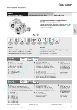
high temperature, optical 5803 / 5823 (shaft / hollow shaft) Push-Pull / RS422
www.HydroSanatSharif.com
The incremental encoders of the high temperature series
5803 / 5823 can be used at up to max. 110°C.
The high heat resistance – at the same time as high speed – make
these encoders the ideal solution for all applications in a high
temperature environment.
Incremental encoders
RoHS
-20°... +110°C IP
High rotational Temperature High protection High shaft load Shock / vibration Magnetic field Short-circuit Reverse polarity Optical sensor
speed range level capacity resistant proof proof protection
Powerful Flexible
• Can be used at temperatures of up to max. 110°C. • Various connection types for different application purposes.
• High resolution up to 5000 pulses per revolution. • Shaft or hollow shaft version.
• Maximum speed of 12000 revolutions per minute. • With push-pull or RS422 interface.
Order code 8.5803 . X X X X . XXXX
Shaft version Type a b c d e
a Flange c Output circuit / power supply e Pulse rate
1 = clamping flange ø 58 mm [2.28“] 4 = RS422 (with inverted signal) / 5 V DC 25, 50, 60, 100, 125, 200, 250,
2 = synchro flange ø 58 mm [2.28“] 5 = RS422 (with inverted signal) / 10 ... 30 V DC 256, 300, 360, 500, 512, 600,
P = synchro flange ø 63.5 mm [2.5“] 6 = Push-Pull (with inverted signal) / 10 ... 30 V DC 720, 800, 1000, 1024, 1200,
M = square flange 63.5 mm [2.5“] 7 = Push-Pull (without inverted signal) / 10 ... 30 V DC 1250, 1500, 2000, 2048, 2500,
3000, 3600, 4000, 4096, 5000
b Shaft (ø x L), with flat d Type of connection (e.g. 100 pulses => 0100)
1 = ø 6 x 10 mm [0.24 x 0.39“] 1 = axial cable, 1 m [3.28‘] TPE
2 = ø 10 x 20 mm [0.39 x 0.79“] 2 = radial cable, 1 m [3.28‘] TPE Optional on request
P = ø 3/8’’ x 7/8” 1) 3 = axial M23 connector, 12-pin, without mating connector - other pulse rates
5 = radial M23 connector, 12-pin, without mating connector
W = radial MIL connector, 7-pin, without mating connector 2)
Y = radial MIL connector, 10-pin, without mating connector
Order code 8.5823 . X X X X . XXXX
Hollow shaft Type a b c d e
a Flange c Output circuit / power supply e Pulse rate
1 = with hollow shaft and spring element, short 1 = RS422 (with inverted signal) / 5 V DC 25, 50, 60, 100, 125, 200, 250,
3)
2 = with blind hollow shaft and spring element, short 4 = RS422 (with inverted signal) / 10 ... 30 V DC 256, 300, 360, 500, 512, 600,
3 = with hollow shaft and stator coupling, ø 65 mm [2.56“] 3 = Push-Pull (with inverted signal) / 10 ... 30 V DC 720, 800, 1000, 1024, 1200,
4 = with blind hollow shaft and stator coupling, ø 65 mm [2.56“] 2 = Push-Pull (without inverted signal) / 10 ... 30 V DC 1250, 1500, 2000, 2048, 2500,
3)
3000, 3600, 4000, 4096, 5000
b Hollow shaft d Type of connection (e.g. 100 pulses => 0100)
1 = ø 6 mm [0.24“], IP40 1 = radial cable, 1 m [3.28‘] TPE
2 = ø 6 mm [0.24“], IP66 2 = radial M23 connector, 12-pin, Optional on request
3 = ø 8 mm [0.32“], IP40 without mating connector - other pulse rates
4 = ø 8 mm [0.32“], IP66
5 = ø 10 mm [0.39“], IP40
6 = ø 10 mm [0.39“], IP66
7 = ø 12 mm [0.47“], IP40
8 = ø 12 mm [0.47“], IP66
1) Only in conjunction with flange M or P. 2) Only with output circuit 7. 3) Insertion depth ) 30 mm [1.18“].
© Fritz Kübler GmbH, subject to errors and changes. 02/2015 www.kuebler.com 75