
Page 149 - Keubler Motion Sensors
P. 149
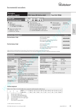
Incremental encoders


             Bearingless
             zero pulse, magnetic            RI50 / Limes LI50 (hollow shaft)    Push-Pull / RS422
              www.HydroSanatSharif.com
             Order code                  8.LI50 . X 1   X X . 1  XXX
             Sensor head Limes LI50         Type    a   b c   d   e

              a     Model                    c     Type of connection            d    Reference signal     Stock types
              1  =  IP67, standard            1  = radial cable, 2 m [6.56‘] PUR          1  =  separate index signal    8.LI50.1121.1032
              2  = IP68 / IP69k and humidity tested    A =  radial cable, special length PUR *)        (linked with A and B)
                   acc. to EN 60068-3-38, EN 60068-3-78   *)   Available special lengths (connection type A):
                                                   3, 5, 8, 10, 15 m [9.84, 16.40, 26.25, 32.80, 49.21‘]    e     Interpolation factor
              b     Output circuit / Power supply        order code expansion .XXXX = length in dm        032, 050, 064, 100
              1  =  RS422 / 4.8 ... 26 V DC        ex.: 8.LI50.111A.1032.0030 (for cable length 3 m)
              2  =  Push-Pull / 4.8 ... 30 V DC                                                                     Incremental  encoders


             Accessories / Display type 572                                                           Order no.
            Position display, 6-digit                          with 4 fast switch outputs
                                                                 and serial interface               6.572.0116.D05
                                                               with 4 fast switch outputs and serial interface
                                                               and scalable analogue output         6.572.0116.D95
            Position display, 8-digit                          with 4 fast switch outputs
                                                                 and serial interface               6.572.0118.D05
                                                               with 4 fast switch outputs and serial interface
                                                               and scalable analogue output         6.572.0118.D95
            Further accessories can be found in the accessories section or in the accessories area of our website at: www.kuebler.com/accessories
            Additional connectors can be found in the connection technology section or in the connection technology area of our website at: www.kuebler.com/connection_technology

             Technical data

             Mechanical characteristics                         Electrical characteristics
             Maximum speed   12000 min -1                       Output circuit     RS422        Push-Pull
             Protection   model 1  IP67 acc. to EN 60529            Power supply   4.8 ... 26 V DC      4.8 ... 30 V DC
                       model 2  IP68 / IP69k acc. to EN 60529, DIN 40050-9      Power consumption (no load)  typ. 25 mA      typ. 25 mA
                              and humidity tested                                  max. 60 mA      max. 60 mA
                              acc. to EN 60068-3-38, EN 60068-3-78
                                                                Permissible load/channel   max. 20 mA
             Working temperature   -20°C ... +80°C  [-4°F ... +176°F]
                                                                Min. pulse edge interval   1 µs
                                  2
             Shock resistance   5000 m/s , 1 ms
                                                                Signal level    HIGH   min. 2.5 V      min. +V - 2.0 V
                                  2
             Vibration resistance   300 m/s , 10 ... 2000 Hz                   LOW   max. 0.5 V      max. 0.5 V
             Pole gap          5 mm from pole to pole           Reference signal   fixed
             Housing (sensor head)   aluminium                  System accuracy    typ. 0.3° with shaft tolerance g6
                                                 2
             Cable            2 m [6.56‘] long, PUR 8 x 0.14 mm [AWG 26],
                               shielded, may be used in trailing cable installations
             Status LED   green   pulse index
                         red   error; speed too high or magnetic fields too weak
                              (8.LI50.XXXX.X050 and 8.LI50.XXXX.X250)
             CE compliant acc. to      EMC guideline 2004/108/EC
                              RoHS guideline 2011/65/EU

            Terminal assignment
             Output circuit   Type of connection   Cable (isolate unused wires individually before initial start-up)
                                  Signal:       0 V   +V    A          B           0           )
                1, 2       1, A
                                  Cable colour:    WH    BN    GN    YE    GY    PK    BU    RD    shield  1)
            +V:    Encoder power supply +V DC
            0 V:    Encoder power supply ground GND (0 V)
            A,  :    Incremental output channel A / sine signal
            B,  :    Incremental output channel B / cosine signal
            0,  :   Reference signal
            ):    Plug connector housing (shield)


            1)  Shield is attached to connector housing.
            © Fritz Kübler GmbH, subject to errors and changes. 02/2015                        www.kuebler.com  147