
Page 113 - Keubler Motion Sensors
P. 113
Incremental
Incremental encodersencoders
Standard
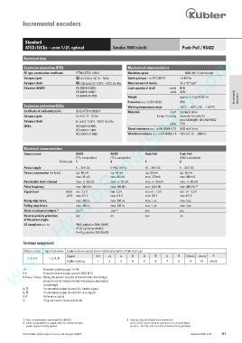
ATEX / IECEx – zone 1 / 21, optical Sendix 7000 (shaft) Push-Pull / RS422
www.HydroSanatSharif.com
Technical data
Explosion protection ATEX Mechanical characteristics
-1
EC type-examination certificate PTB09 ATEX 1106 X Maximum speed 6000 min (continuous)
Category (gas) II 2 G Ex d IIC T4 - T6 Gb Starting torque – at 20°C [68°F] < 0.05 Nm
-6
Category (dust) II 2D Ex tb IIIC T135°C - T85°C Db IP6x Mass moment of inertia 4.0 x 10 kgm 2
Explosionsschutz EN 60079-0:2009; Load capacity of shaft radial 80 N
Directive 94/9/EC
EN 60079-1:2007; axial 40 N
EN 60079-31:2009 Weight approx. 1.3 kg [45.86 oz] Incremental encoders
Protection acc. to EN 60529 IP67
Explosion protection IECEx Working temperature range -40°C ... +60°C [-40 ... +140°F]
Certificate of conformity (CoC) IECEx PTB 13.0026 X Materials shaft stainless steel
Category (gas) Ex d IIC T4 - T6 Gb flange / housing seawater durable Al,
Category (dust) Ex tb IIIC T135°C - T85°C Db IP6x type AlSiMgMn (EN AW-6082)
cable PUR
IECEx IEC 60079-0:2007; 2
IEC 60079-1:2007; Shock resistance acc. to EN 60068-2-27 2500 m/s , 6 ms
2
IEC 60079-31:2008 Vibration resistance acc. to EN 60068-2-6 100 m/s , 55 ... 2000 Hz
Electrical characteristics
Output circuit RS422 RS422 Push-Pull Push-Pull
(TTL compatible) (TTL compatible) (7272 compatible)
Ordercode 1 4 5 2
Power supply 5 ... 30 V DC 5 V DC (±5 %) 10 ... 30 V DC 5 ... 30 V DC
Power consumption (no load) typ. 40 mA typ. 40 mA typ. 50 mA typ. 50 mA
max. 90 mA max. 90 mA max. 100 mA max. 100 mA
Permissible load / channel max. +/- 20 mA max. +/- 20 mA max. +/- 20 mA max. +/- 20 mA
Pulse frequency max. 300 kHz max. 300 kHz max. 300 kHz max. 300 kHz 1)
Signal level HIGH min. 2.5 V min. 2.5 V min +V - 1.0 V min. +V - 2.0 V
LOW max. 0.5 V max. 0.5 V max. 0.5 V max. 0.5 V
Rising edge time t r max. 200 ns max. 200 ns max. 1 µs max. 1 µs
Falling edge time t f max. 200 ns max. 200 ns max. 1 µs max. 1 µs
3)
2)
3)
Short circuit proof outputs yes yes yes yes
Reverse polarity protection yes no yes no
of the power supply
CE compliant acc. to EMC guideline 2004/108/EC
ATEX guideline 94/9/EC
RoHS guideline 2011/65/EU
Terminal assignment
Output circuit Type of connection Cable (isolate unused wires individually before initial start-up)
Signal: 0 V +V A B 0 0 Vsens +Vsens )
1, 2, 4, 5 1, 2, A, B
Cable marking: 1 2 3 4 5 6 7 8 9 10 shield
+V: Encoder power supply +V DC
0 V: Encoder power supply ground GND (0 V)
0 Vsens / +Vsens: Using the sensor outputs of the encoder, the voltage
present can be measured and if necessary increased
accordingly.
A, : Incremental output channel A / cosine signal
B, : Incremental output channel B / sine signal
0, : Reference signal
): Plug connector housing (shield)
1) Max. recommended cable length 30 m [98.43‘]. 3) Only one channel allowed to be shorted-out:
2) Short-circuit with 0 V or output, only one channel at a time, at +V= 5 V DC, short-circuit to channel, 0 V, or +V is permitted.
power supply correctly applied. at +V= 5 ... 30 V DC, short-circuit to channel or 0 V is permitted.
© Fritz Kübler GmbH, subject to errors and changes. 02/2015 www.kuebler.com 111